
How to Build an Alarm Circuit with Transistors
In this circuit, we will build an alarm circuit using transistors.
This is a circuit in which once the alarm is activated, the output device stays on even if signal which activated it goes off.
For example, in this circuit, we will sound a buzzer when enough input voltage is fed into the base of the first transistor.
We will use 2 transistors in this circuit. The transistors form a latch circuit, meaning once enough voltage goes into the base of the first transistor, it powers on the second transistor. Even if the power to the first transistor then goes out, the second transistor still powers it on, so the output, which is the buzzer, still sounds.
So once we have enough power to the base of the first transistor, our buzzer will turn on and stay on, even if the power is removed from the base of the first transistor. The only way to shut off the circuit is to shut off the power to the collector of the second transistor.
Thus, this circuit mimics an alarm circuit.
Latches function well and are used frequently in alarm circuits. If triggered once, the sirens will flash indefinitely or the buzzer will sound indefinitely until someone manually removed the power.
In this circuit, we will use 2 transistors, the BC547 and the BC557, to form a latch.
Components Needed
- BC547 NPN transistor
- BC557 PNP transistor
- 2 2.2KΩ resistors
- 1KΩ resistor
- Buzzer
- Power source
The BC547 is a BJT NPN transistor.
The BC547 can handle a maximum voltage of 65V at its collector.
The BC557 is a BJT PNP transistor.
The BC557 can handle a maximum voltage of 65V at its emitter
The resistors serve for biasing purposes.
In this circuit, we will latch on a buzzer.
Alarm Circuit Built with Transistors
The alarm circuit we will build using transistors is shown below.
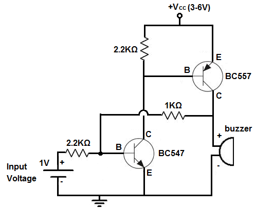
So, for this circuit, the first transistor is the BC547 while the second is the BC557.
So the first 2.2KΩ resistor that goes into the base of the BC547 is used to limit current that goes to the BC547. You always need resistors for the bases of BJT transistors. If you do not use resistors and resistors that have enough resistance, you can fry transistors. And it's pretty easy to do. When feeding current into the base of a transistor, you have to limit the current entering the base. If you don't, it will fry the transistor. It'll smoke and it will be nonfunctional afterwards. So, again, this 2.2KΩ resistor limits current going into the BC547 transistor.
The 2.2KΩ resistor at the top of the circuit limits current going into the base of the BC557 transistor. This resistor serves the same purpose as the other 2.2KΩ resistor but with the BC557.
The 1KΩ resistor is used to limit current going into the base of the BC547 from the output of the BC557.
There are 2 possible currents being fed into the base of the BC547 transistor. There is the current produced from the input voltage source, VIN. And then there's current fed into the BC547 from the output of the BC557. The first current from the input voltage source is needed to trigger on the latch circuit. And the current from the output of the BC557 being fed into the BC547 is needed to keep the circuit latched on. The BC547 provides the continouous current to the base of the BC547 so that it continually stays on, once it's initially fed on by the input voltage source. The 2.2KΩ resistor limits current to the base of the BC547 from the input voltage source. And the 1KΩ resistors current to the base of the BC547 from the output current that's fed into it from the BC557.
The buzzer along with the 470Ω resistor are the output of the circuit.
How the Circuit Works
This is how the latch circuit operates.
When 0.65V is fed into the base of the BC547 transistor, it turns on. Once it turns on, current flows from VCC down to the base of the BC557 transistor. This, in turn, turns on the BC557 transistor. Current now flows from the collector of the BC557 in 2 directions. Some of the current flows to turn on the load, which in this case is the buzzer. And some of the current flows into the base of the BC547 transistor. This is really how the latch is formed. Once we turn on the BC547, it, in turn, turns on the BC557. And then the BC557 provides continuous current to the base of the BC547, so that it remains on, even if we turn off the input voltage supply, VIN. The only way to turn off the circuit and reset it, then, is to turn off the supply voltage VCC. Turning off the input voltage, VIN will have no effect. Once we turn it on the input voltage once to the threshold voltage of 0.65V, which is the voltage needed to turn on the BC547, it's latched on.
So this is how a latch circuit can be built with transistors.
It perfectly mimics an SCR, a silicon-controlled rectifier.
It functions as a digital latch.
And it can be used well for alarm circuits. It has many practical uses.
Related Resources
How to Build a Motion Detector Alarm Circuit
How to Build a Vibration Alarm Circuit
How to Build a Light Alarm Circuit
How to Build a Sound Alarm Circuit
How to Build a Heat Alarm Circuit
How to Build a Tilt Alarm Circuit
How to Build a Door Alarm Circuit