
How to Build a Vibration Alarm Circuit

In this project, we will build a vibration alarm circuit.
This is a circuit in which an alarm will be triggered when a sufficient vibration is detected.
This alarm can be very useful in a room or an area that should normally have no movement at all in it. In a totally still room with no movement, no vibration will be detected and the alarm will not go off. Once the circuit detects a vibration, which could represent that someone can entered the room or there is some type of movement disturbance, the alarm will be triggered.
In our circuit, specifically, we will design it so that an LED will turn on and stay on once a vibration is detected.
This will alert us that a vibration has been detected and someone has entered a room and is moving around in the vicinity of where the circuit
is located.
Components Needed
- MEAS Piezo vibration sensor
- Arduino Board
- LED
The sensor we will use to detect these movements is a piezo vibration sensor from Measuremenet Specialists (MEAS).
The piezo vibration sensor is from the company MEAS. It can be obtained from a number of online retailers for a very low price (under $5). Follow this link to the piezo sensor offered by Sparkfun- Sparkfun- Piezo vibration sensor.
The piezo sensor is a 2-pin device. One pin will be represents the positive terminal, while the other pin represents the negative or ground terminal.
Below is the pinout of the sensor:

When there is a sufficient enough of a vibration, the vibration sensor will produce a spike in voltage in response. This voltage
may be as high as ±90V. The voltage is an analog voltage. It is this voltage produced that can trigger on another device. In this circuit, we
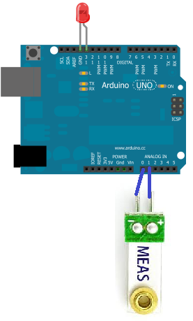
connect this output voltage to the analog pins 0 and 1 on the arduino board. When vibration is detected, the piezo sensor creates a voltage
on the analog line. The arduino pins detect this and through our software, we can program it so that when this analog voltage is detected,
the LED on digital pin 8 of the arduino turns on.
Vibration Alarm Circuit
Below is the vibration alarm circuit:
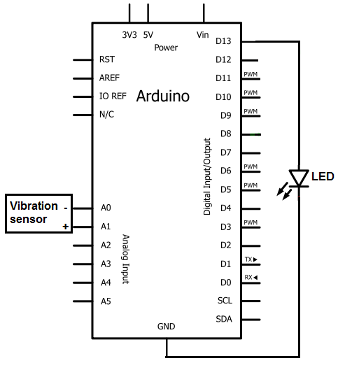
Below is the schematic of the circuit above:
So this circuit works through vibration detection.
Once the piezo vibration sensor senses a sufficient enough vibration, it produces a voltage in response to this movement. The voltage can be very large, but the arduino analog terminals have built-in resistance in order to attenuate this signal. So you don't have to worry about this extremely large voltage signal damaging the arduino board. It is attenuated to a low enough level that no damage will occur.
The voltage signal that the piezo sensor creates is an analog voltage. This is why the piezo sensor must be
connected to the analog terminals of the arduino board. Only the analog terminals can detect and measure analog signals.
Once the arduino board
detects this analog voltage, our software code will then trigger the LED to turn on and stay on. The LED we will turn on, we will connect
to digital pin, D13. The positive terminal of the LED (the cathode) will go into terminal D13 of the arduino board. The negative terminal
of the LED (the cathode) will connect to the ground terminal of the arduino. The pin D13 has built-in resistance, just like the analog terminals,
so that no external resistance is necessary to limit current to the LED.
Code
The code needed to turn on an LED when vibration is detected and for the LED to stay on unless power shuts it off is shown below.
int GroundPin= 1;
int sensePin= 2;
int LEDPin= 13;
int threshold= 500;
void setup()
{
Serial.begin(9600);
pinMode(GroundPin, OUTPUT);
digitalWrite(GroundPin, LOW);
pinMode(LEDPin, OUTPUT);
}
void loop()
{
int reading= analogRead(sensePin);
Serial.println(reading);
if (reading > threshold)
{
digitalWrite(LEDPin, HIGH);
}
}
The first block of code defines the pin connections. The ground pin (of the sensor) will be put in A0 of the arduino. The sensepin will be placed in A1. And the LEDPin will be placed in digital pin D13.
The second block of code defines a variable called threshold. This is a very important variable because it represents the analog level at which the LED will be triggered to turn on. The arduino can detect and measure analog values from 0 to 1023. We created it so that once an analog sound vibration reaches 600 or greater, the LED will be triggered on. You can modify this value to be less or greater depending on the amplitude of the vibration you want to be the trigger point. However, a value near 600 is good for all practical purposes. If you lower the threshold value, then the circuit will detect vibrations easier. If you raise the threshold value, the circuit will need greater vibrations in order to trigger.
The third block of code sets up the A0 terminal as the ground pin. It must be set as output and then declared LOW in order to function as a ground. This serves as the ground for the negative lead of the piezo sensor. The LEDPin serves as a digital output pin for the LED we connect to D13, so it must be declared output. We put the line Serial.begin(9600) so that if we want, you can see the values that the arduino is reading from the sensor if you had the line Serial.println(reading), for testing purposes.
The fourth block of code is the loop() function. The reading variable measures the actual voltage on the sensePin of the vibration sensor, which is the positive terminal connected to A1. If the reading is larger than the threshold value, the LED will be triggered to high and turned on and made to stay on. If not, it does not turn on. With this code, we only turn the LED on when the vibration is a large enough amount. If you want, you can set the threshold to a higher amount, so that the LED only turns on for a greater impact force to the sensor. Play around with this to suit your needs.
And this is how a basic vibration alarm circuit functions.
Variations of this circuit can be done to fit your needs. Maybe you don't want a buzzer to sound when vibration is detected. Maybe instead you want siren lights to go off. In that case, you would replace the buzzer with siren lights. You can power any device you want that can act as the alarm, as long as the device receives sufficient power in order to operate. There are many ways the circuit can operate. Customize according to your needs.
Below is the real-life circuit of this project built so that you can see for yourself how it operates.
Related Resources
How to Build a Sound Alarm Circuit
How to Build a Light Alarm Circuit
How to Build a Heat Alarm Circuit
How to Build a Tilt Alarm Circuit
How to Build a Door Alarm Circuit
How to Build a Vibration Motor Circuit
How to Build a Hall Effect Sensor Circuit
How to Build a Touch Sensor Circuit
How to Build an Accelerometer Circuit
How to Build a Motion Detector Circuit
How to Build a Motion Detector Alarm Circuit
How to Build a Piezo Knock Sensor Circuit