
How to Build a Light Alarm Circuit
In this project, we will go over how to build a light alarm circuit.
This is a circuit that will go off once it detects a certain amount of light. Once the light the circuit is exposed to increases to a certain level, a loud buzzer will go off, alerting us to this.
In doing this, this circuit will alert us to when it is exposed to a certain amount of direct light.
So the alarm will not go off when the circuit is exposed to a darkly lit area but if taken out and exposed to bright light like of sunlight or the light of a room will go off.
An example of where we could use this circuit is in the following real-world example. We could place this device
in a very dark area such as the drawer of a cabinet. Let's say
we have a lot of valuables which we want to protect in a chester drawer such as jewelry. And we regularly keep this drawer closed. Being
closed, no light enters and the circuit is in enclosed in a dark area with no light. Under these conditions, the alarm does not go off
because it is not exposed to light. However, say, if a thief breaks into the house and opens this drawer either during the day or at a night,
shining a flashlight into the drawer. Now exposed to light, the circuit will trigger and buzz an alarm. So the housekeeper can know if
someone has broken in by hearing this device. This one possible application of this light alarm circuit we will build.
Components Needed to Build Light Alarm Circuit
- 200KΩ Photoresistor
- C106B SCR
- Buzzer or LED
- 5 AA Batteries or Dual Power DC Power Supply
What we will use for this circuit is a 200KΩ photoresistor. Photoresistors are also called light-dependent resistors (LDRs). This can be obtained at digikey at the following link: Digikey- 200KΩ Photoresistor. If you don't have a 200KΩ photoresistor, just make sure to use one that has a dark resistance of 100KΩ or greater.
A photoresistor is a resistor whose resistance changes according to the amount of light that it is exposed to. When exposed to total darkness, the photoresistor's resistance is very high. This is called its rated dark resistance. For example, in our case we are using a 200KΩ photoresistor. This means that when exposed to total darkness, its resistance will be around 200KΩ. As the photoresistor is exposed to increasing amounts of light, its resistance begins to drop and drop significantly. There is another rating on the datasheet labeled cell resistance @ illuminance. This is the resistance that the photoresistor will drop to when exposed to bright light, typically 10 lux.
So a photoresistor is basically a device that gives off very high resistance at dark light levels and low resistance at high light levels. Being that it does this, it acts as a sensor for light, or a photosensor.
When exposed to a darkly lit area such as the insides of a chester drawer, the resistance will be very high. Since the resistance is so high, practically no current will flow through the circuit, so nothing turns on. If the circuit is exposed to light, then the resistance drops significantly, allowing sufficient current to be able to flow which allows electronic components to turn on.
With the photoresistor focusing as the heat sensor, the other significant component is the silicon-controlled rectifier (SCR).
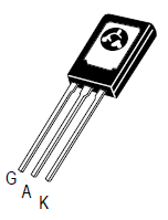
The SCR is a 3-pin device composed of a gate, an anode, and a cathode.
Like a transistor, when the SCR receives sufficient voltage at its gate terminal, it conducts across from anode to cathode. Without this voltage at its gate, no current can flow from anode to cathode. With this gate voltage, current can flow and power the load connected to the anode of the SCR. However, unlike a transistor, a SCR is different in that once it receives sufficient voltage at its gate, it conducts indefinitely from anode to cathode- unless power is disconnected from the anode. So while a transistor needs ongoing current at its base or gate terminal to conduct current across its junction, an SCR only needs to be triggered once to remain on. Thus, it acts like a latching circuit in that once it is turned on, it latches on and stays on.
Looking at the above SCR, with it turned to its back surface, the pin to the leftmost is the gate terminal, the middle pin is the anode, and the rightmost pin is its cathode.
This is the datasheet for the SCR: C106B SCR Datasheet.
The photoresistor will be connected to the gate of the SCR. When the light increases to a certain level,
the resistance drops, allowing current to flow through and trigger the gate of the SCR. The SCR, then triggered, will
then turn on the load connected to it, which in our case is a buzzer or an LED.
Light Alarm Circuit Schematic
The schematic for the light alarm circuit is shown below:
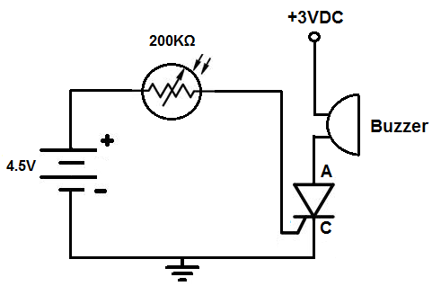
This is the circuit we will build.
In a darkly lit area, the photoresistor will offer very high resistance, near its rated value of 200KΩ. At this resistance, practically no current flows so the SCR gate does not get triggered.
However, when the photoresistor is exposed to a significant amount of light, its resistance drops significantly. Enough current now flows through the circuit to trigger the gate of the SCR. Once the gate of the SCR is triggered, current now flows across from its anode to cathode and turns on the buzzer. Once triggered, the SCR stays on, just like an alarm, stimulating an alarm circuit.
And this is how this light alarm circuit works.
Different variations can be done for this circuit. If you don't want a buzzer to go off but instead want an
LED to light, swap out the buzzer with an LED. But for an LED, make sure to add about a current-limiting resistor, of about
200Ω-400Ω. You can add device that you want to go off once the SCR is triggered. Customize the circuit to suit your preferences.
Below is a visual demonstration of the light alarm circuit, so that you can see how it operates.
Also if you want to see a variation of this circuit which both lights an LED and sounds a buzzer off, see
Light Alarm Circuit (LED and Buzzer go off). This is the same circuit as above, only
with a buzzer placed in parallel with the LED.
Related Resources
How to Build a Sound Alarm Circuit
How to Build a Heat Alarm Circuit
How to Build a Vibration Alarm Circuit
How to Build a Tilt Alarm Circuit
How to Build a Door Alarm Circuit
How to Build a Motion Detector Alarm Circuit
How to Build a Hall Effect Sensor Circuit
How to Build a Vibration Detector Circuit
How to Build a Dark-activated Switch
How to Build a Dark-activated Light Circuit