How to Build a Tilt Alarm Circuit

In this project, we will go over how to build a tilt alarm circuit.
This is a circuit where an alarm will go off once the circuit is tilted. Once the circuit is tilted beyond a certain degree, a loud buzzer will go off, alerting us to this.
In doing this, this circuit will alert us to when it is tilted or completely tipped over.
Many different types of electronics have tip-over protection circuits. One such device are heaters. Usually, though, the heater will be wired so that it will just shut off when it is tipped over. If you want to learn how to build a circuit that simply shuts off when it is tilted or tipped over, see How to Build a Simple Tilt Sensor Circuit.
However, for this circuit, we are not simply going to shut off the circuit when it tilts or tips over. Instead we are going to add slight more sophistication so that an alarm goes off instead during a tilt or tipover.
Instead of just simply shutting off during a device tipover, many times you may want to be alerted to this. For example, imagine if you have vending machine and some people come over and tilt and tip it over. You wouldn't just want the vending machine to shut off. You would want to be alerted of this and have alarms sound off as to know that a group of people have tipped over or are trying to tip over your vending machine. So you can see the type of application this type of circuit could have.
In our circuit, we will make it so that a loud buzzer goes up if our circuit device tilts.
Components Needed to Build Tilt Alarm Circuit
- Tilt Sensor
- C106B SCR
- Buzzer or LED
- 9 volt battery or DC power supply
The tilt sensor is the component which is used to detect if the circuit is tilted.
A tilt sensor is a sensor that can allow us to detect the orientation or inclination of a circuit.
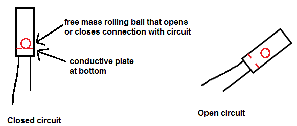
Tilt sensors work by having a free moving mass, usually a rolling ball, in them with a conductive plate beneath. When the sensor is completely upright, the ball falls to the bottom of the sensor, touching the electrical connection path, closing the electrical connection from the 2 end terminals, allowing current to be able to flow. When the sensor is tilted, the ball does not fall to the bottom and close the electrical conductive path. Therefore, the conductive path is open and no current can flow.
The diagram below illustrates the concept of how a tilt sensor works:
With the tilt sensor detecting tilt and orientation in our cirucit, the other significant component is the silicon-controlled rectifier (SCR).
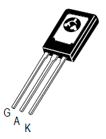
The SCR is a 3-pin device
composed of a gate, an anode, and a cathode.
Like a transistor, when the SCR receives sufficient voltage at its gate terminal, it conducts across from anode to cathode. Without this voltage at its gate, no current can flow from anode to cathode. With this gate voltage, current can flow and power the load connected to the anode of the SCR. However, unlike a transistor, a SCR is different in that once it receives sufficient voltage at its gate, it conducts indefinitely from anode to cathode- unless power is disconnected from the anode. So while a transistor needs ongoing current at its base or gate terminal to conduct current across its junction, an SCR only needs to be triggered once to remain on. Thus, it acts like a latching circuit in that once it is turned on, it latches on and stays on.
Looking at the above SCR, with it turned to its back surface, the pin to the leftmost is the gate terminal, the middle pin is the anode, and the rightmost pin is its cathode.
This is the datasheet for the SCR: C106B SCR Datasheet.
For our circuit we will supply 9 volts DC to it. This 9VDC can be supplied either from 4 AA batteries connected in series
or by a DC power supply.
Tilt Alarm Circuit Schematic
The schematic for the light alarm circuit is shown below:
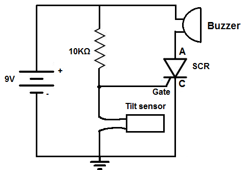
We will use a tilt sensor in conjunction with a 10KΩ resistor- the 2 of these components form a voltage divider circuit. The 9 volts that are supplied to this circuit are in parallel with the 10KΩ resistor and the tilt sensor circuit, with the gate of the SCR being connected to the middle of the resistor and tilt sensor.
When the circuit is upright (not tilted), the tilt sensor forms an electrical path to the ground of the circuit. Since the tilt sensor offers such a low resistance path, most current goes through the tilt sensor and to ground, bypassing the gate of the SCR. Being that most goes through ground through the tilt sensor and not through the gate of the SCR, the SCR does not get triggered and remains off. Therefore, the buzzer that will be connected to the anode of the SCR does not turn on.
However, when the circuit is tilted, the tilt sensor does not make electrical connection, so it acts as an open cirucit. Now the tilt sensor offers extremely high, practically infinite, resistance. Therefore, no current flows through the sensor and to ground. Instead the current will flow through the gate of the SCR, triggering the SCR to turn on. The buzzer at the anode will now sound off and stay on. Being that an SCR stays powered on once triggered, the buzzer will only turn off if the power, the 9VDC, is completely shut off.
And this is how this tilt alarm circuit works.
Different variations can be done for this circuit. If you don't want a buzzer to go off but instead want something else to, swap out the buzzer for that component. You can add device that you want to go off once the SCR is triggered. Customize the circuit to suit your preferences.
Watch the video of this circuit below to see it in action. For the video, we used an LED instead of a buzzer.
Related Resources
How to Build a Sound Alarm Circuit
How to Build a Heat Alarm Circuit
How to Build a Vibration Alarm Circuit
How to Build a Motion Detector Alarm Circuit
How to Build a Door Alarm Circuit
How to Build a Hall Effect Sensor Circuit
How to Build a Vibration Detector Circuit