How to Build a Battery Tester
In this project, we will go over how to build a battery tester, so that we can just check whether a battery is good or bad.
This is a method which can work if you do not have a voltmeter. With a voltmeter, checking a battery would be a very simple process. But if you do not have one, there are other ways to go about checking the level of a battery to see whether it is still good or not.
Now we will build a circuit which can show whether the voltage that a battery is outputting is above or below a certain level.
We can adjust the circuit so that any type of battery can be tested with this circuit. It would just require adjustment of the voltage.
How we will build this circuit is mainly through the use of a voltage comparator IC. A voltage comparator is a chip which can differentiate whether voltage is above a certain reference level or below a certain reference level. Therefore, with a voltage comparator, we can check whether the voltage from a battery is above a certain reference voltage level or below. And we can adjust this reference voltage level to any voltage we want. So if we want to test a AA battery, which is a battery which contains 1.5V (or a little above) when brand new, we can set the reference voltage to about 1.4V. If the battery's voltage is above this level, then we know that the battery is good. It's at full strength. If the voltage is below this level, then we know that the battery most likely is used and depleted. So we can discard it.
So this circuit tests voltage levels based on the use of a voltage comparator. And we'll see how this works.
Components Needed
- LM393 Voltage Comparator IC
- 470Ω Resistor
- Red LED
- Jumper wires
- Battery to test
- Battery holder
One of the main components we will use for this circuit is the LM393 voltage comparator chip. A voltage comparator will allow us to determine the voltage level which a battery contains. Once we feed the voltage comparator a certain voltage reference level, we can then connect the battery to determine if its voltage is above or below this level.
This voltage comparator IC can be obtained at tayda electronics at the following link: Tayda Electronics- LM393 Voltage Comparator.
The LM393 is a dual differential comparator; this means that it accepts 2 inputs for comparison.
It compares these voltage inputs and determines which is the larger value. Based on this, electronic decisions can be made based on which input is greater and which is smaller. Thus, a comparator is very useful in circuits where we measure levels and want our circuit to act a certain way based on whether the level of an input is greater or smaller than a certain threshold.
Before we actually build our comparator circuit, we will go over the pinout of an LM393 comparator IC, so that you know what each pin is and what each pin does.
An LM393 is a 8-pin chip.
Its pinout is shown below:
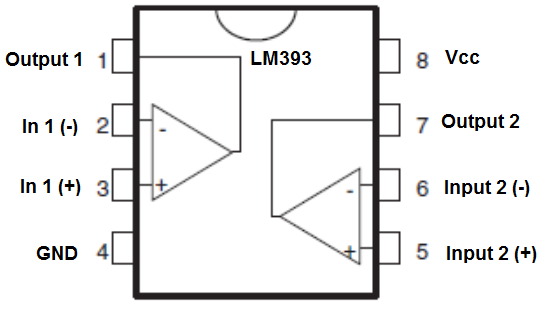
The LM393 has 2 power inputs. These are labeled VCC and GND. VCC is where the positive terminal of the voltage supply gets inserted into. This supply voltage can be as high as 36V. GND is where the ground wire of the voltage source gets connected to. These 2 terminals complete the power path for the LM393 chip and gives it the power it needs to function.
Apart from power, we now deal with the 2 operational amplifiers that are internally within the chip. Each op amp has 2 inputs and one output. These op amps are independent of each other, meaning each one acts independently to give its own output value (based on their 2 input values). In1 (-) and In2 (-) are the inputs for the op amp 1. Output 1 is the output of this op amp. In2 (-) and In2 (+) are the inputs for op amp 2. Output 2 is the output of this op amp.
For our circuit, we will only use one op amp; the other will be left unconnected, so none of the pins of the other op amp will be used.
Using both op amps is only needed when we deal with more complex circuits in which we need to monitor multiple levels. If we are only checking one level, then we need only one op amp.
Now that the pinout is explained, we will now explain how the chip works.
So, as explained, we have to give power to the chip in order for it to work. Once we have power to the chip, the next thing we must do is supply the op amp with 2 inputs for comparison, the 2 inputs whose voltage values we want to compare. After we have done this, we can now get an output. This output value will appear at the output terminal of the LM393.
If the voltage at the inverting terminal is greater than the voltage at the noninverting terminal, then the output of the op amp will be drawn up to Vcc. If the voltage at the inverting terminal is less than the noninverting, then the output of the op amp is drawn down to GND.
This means that when the inverting terminal voltage is greater, the load connected to output can be powered on. When the noninverting terminal voltage is greater, the load connected to output will be powered off. So if an LED is connected to output, it will turn on when the inverting voltage is greater and turn off when the noninverting voltage falls below the inverting voltage.
So now that the voltage comparator is fully explained, the only other components we need are an LED, a current-limiting resistor to keep the LED from burning out, a power source,
and the battery which you want to test. We will also need a battery holder so that we can connect to the circuit.
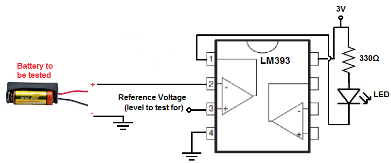
Battery Tester Circuit Schematic
The schematic of the battery tester we will build is shown below:
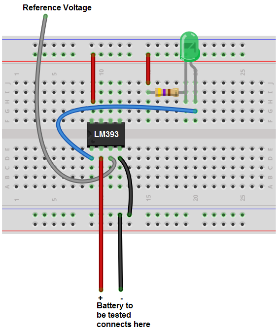
This circuit built on a breadboard schematic will look like the following shown below.
We now explain how the circuit works.
We feed a reference voltage level into the noninverting terminal of the op amp. This voltage serves as the central voltage point which we will measure the battery we're testing against. This reference voltage sets the level that we want to compare the voltage from the battery against. If we set the reference voltage level at 1.2V, then when we connect the battery, we can then determine whether the voltage from the battery is below or above this reference voltage level of 1.2V. Therefore, we can tell whether or not the battery is good. Once a AA battery gets to less than 1.2V, then it's no longer good and should be discarded. So this is a good level we can set the reference voltage to, but if you want to see the battery is at full strength, then it should be above 1.5V when fully strong and brand new. So you can even change the reference voltage to a higher value such as 1.5V or a little below such as 1.45V or so. For a 9V battery, we then use an entirely reference voltage. We may use a reference voltage of 9V or 8.9V or so.
How this circuit works is we set up the reference voltage to the noninverting terminal. This creates the level which we can compare against. When the voltage at the inverting terminal is greater than at the noninverting terminal, then this means that the voltage from the battery is greater than the reference level. This means that the battery is good. So the green LED at the output of the op amp lights up. When the voltage from the battery is lower than the reference voltage, then the voltage at the inverting terminal is less than at the noninverting terminal, and the LED does not light up. It stays off. This shows that the battery is no good. If the LED does not light up after the battery is connected, then this is a signal that the battery is no good.
So if the LED lights up, the battery is good. If it does not, then the battery is bad. So the green LED really symbolizes that the battery is good.
So this is one way a battery tester can be done. Even though this seems really complicated for just a simple battery tester, it's a really good circuit for a foundation in which
we can create any voltage level and see whether a device is outputting a voltage above or below this level, so it can be used as for many other circuits, so it's a good foundation for measuring
voltage levels.
Related Resources
How to Build a Dark-activated Light Circuit
How to Build a Hall Effect Sensor Circuit
How to Build a Touch Sensor Circuit
How to Build a Reed Switch Circuit