
Capacitors in Series and in Parallel

In this article, we will go over how capacitors add in series and how they add in parallel.
We will go over the mathematical formulas for calculating series and parallel capacitance so that we can compute
the total capacitance values of actual circuits.
Capacitors in Series
Capacitors in series are capacitors that are placed back-to-back with the negative electrode of one capacitor connecting to the positive electrode of the other.
Below is a circuit where 3 capacitors are placed in series.
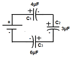
You can see the capacitors are in series because they are back-to-back against each other, and each negative electrode is connected to the successive capacitor's positive electrode. The best way to think of a series circuit is that if current flows through the circuit, the current can only take one path.
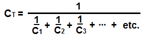
Formula for Adding Capacitors in Series
The formula to calculate the total series capacitance is:
So to calculate the total capacitance of the circuit above, the total capacitance, CT would be:
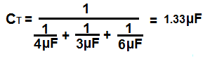
So using the above formula, the total capacitance is 1.33µF.
Note- When capacitors are in series, the total capacitance value is always less than the smallest capacitance of the circuit. In other words, when capacitors are in series,
the total capicitance decreases. It's always less than any of the values of the capacitors in the circuit. The capacitance doesn't increase in series; it decreases.
Capacitors in Parallel
Capacitors in parallel are capacitors that are connected with the two electrodes in a common plane, meaning that the positive electrodes of the capacitors are all connected together and the negative electrodes of the capacitors are connected together.
Below is a circuit where 3 capacitors are in parallel:
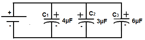
You can see that the capacitors are in parallel because all the positive electrodes are connected (common) together and all the negative electrodes are connected (common) together. The best way to think about parallel circuits is by thinking of the path that current can take. When current is travelling through a parallel circuit, the current can take various paths through the circuits, such as go through any of the branches of the capacitors. In series, this is not the case. Current can only take one path.
Formula for Adding Capacitors in Parallel
The formula to calculate the total parallel capacitance is:
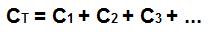
So to calculate the total capacitance of the circuit above, the total capacitance, CT would be:

So using the above formula, the total capacitance is 13µF.
In parallel, capacitors simply add together. So adding up the total capacitance in parallel is much simpler than adding them in series.
In fact, since capacitors simply add in parallel, in many circuits, capacitors are placed in parallel to increase the capacitance. For example, if a circuit designer
wants 0.44µF in a certain part of the circuit, he may not have a 0.44µF capacitor or one may not exist. So what he can do and what is done many times in professional circuits is that 2
0.22µF capacitors would be placed in parallel to give the equivalent 0.44µF capacitance. This is done often in circuits.
Capacitor Circuit in Series and In Parallel
We'll now do a capacitor circuit in which capacitors are both in series and in parallel in the same circuit.
Below is a circuit which has capacitors in both series and parallel:

So how do we add them to find the total capacitance value?
First, we can start by finding the series capacitance of the capacitors in series. In the first branch, containing the 4µF and 2µF capacitors, the series capacitance is 1.33µF. And
in the second branch, containing the 3µF and 1µF capaictors, the series capacitance is 0.75µF. Now in total, the circuit has 3 capacitances in parallel, 1.33µF, 0.75µF, and 6µF. Now, these 3 values
just simply add together for a total capacitance of 8.08µF.
If you want to test the above series and parallel connections out practically, get 2 1µF or whatever capacitors you have, but let them be of the same value. In this example, I'll stick with 1µF capacitors. Now take the capacitors and place them in series. Now take a multimeter and place in the capacitance meter setting and place the probes over the positive electrode of the first capacitor and the negative electrode of the second capacitor. You should read just about 0.5µF, which is half the value. This proves that capacitance is lower when capacitors are connected in series. Now place the capacitors in parallel. Take the multimeter probes and place one end on the positive side and one end on the negative. You should now read 2µF, or double the value, because capacitors in parallel add together. This is a practical, real-life test you can do to show how capacitors work.
Note-The above formulas for measuring the total capacitance works for all types of capacitors, including polar and nonpolar capacitors. However, for polar capacitors,
such as electrolytic and tantalum, the capacitors
must be oriented in the circuit in the correct way. Polar capacitors, in series, must be placed so that the negative electrode of the first capacitor connects to the positive electrode of the
second capacitor, and so forth for all capacitors in series. In parallel, the capacitor electrodes must all be common, all positive electrodes connect together on a common plane and all
negative electrodes connect together on a common plane, which is normally ground. For nonpolar capacitors, including ceramic capacitors, orientation does not matter, since the capacitor
isn't polarized.
Related Resources
Series and Parallel Capacitor Calculator
Capacitor Equations
Capacitance Calculator
Capacitor Charge Calculator
Capacitor Voltage Calculator
Capacitor Impedance Calculator
Capacitor Charging Calculator
Capacitor Discharge Calculator
Capacitor Energy Calculator
Capacitor Voltage Divider Calculator
How to Calculate the Current Through a Capacitor
How to Calculate the Voltage Across a Capacitor