How to Build a DC Motor Driver Circuit
In this project, we will go over how to build a DC motor driver circuit.
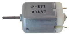
A DC motor driver circuit is a circuit which can turn on and operate a DC motor.
Basically, it is a circuit that gives enough power to drive a DC motor.
You may notice that if you have a battery or DC power supply and you plug the power directly into the terminals of the DC motor, it will turn on and function. When such power is connected directly to the terminals of a DC motor, it receives sufficient voltage and current to power on. It may seem like a DC motor doesn't need a driver circuit, since it works when you connect power directly to it.
However, it is not always the case that direct power can be given to a DC motor. If a motor is attached to the output of a chip or a microcontroller such as an arduino, these terminals do not output adequate current to drive a DC motor. In this case, you would need a driver circuit in order for the DC motor to operate. So, basically when the current level is not adequate to drive a motor, a driver circuit is needed.
So how do we build this driver circuit?
Basically, at the heart of the driver circuit is a transistor, specially a bipolar junction transistor (BJT). The BJT is the central piece of the driver circuit because it provides current amplification. A DC motor is a device that needs a certain level of current, typically about 75mA, depending on the type in use, in order to be driven. Without sufficient current, the motor will not spin. A bipolar junction transistor (BJT) is a current amplifier, so it is the perfect device needed to drive the DC motor. Once we hook up a transistor to the output of a chip and then place the motor on the output of the transistor, through the transistor amplification, there is now enough current to run the DC motor.
A diode is placed in parallel, reverse biased, to the DC motor, because motors, as well as relays, can
produce a very high back EMF voltage when they are turned off due to energy they store in the coils.
This excess voltage can damage the switching transistor. To prevent this, the diode shorts this back EMF out so that
the transistor and other electronic components in the circuit don't get damaged.
Components Needed
- 10KΩ Resistor
- BJT transistor
- Diode
- DC power supply or batteries
The transistor can be any BJT, such as the 2N3904 or the 2N2222. It really doesn't matter.
And the diode can be really any either, such as the 1N4001.
DC Motor Driver Circuit Schematic
The schematic diagram of the DC motor driver circuit is shown below.
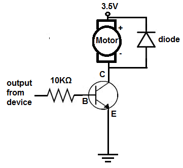
So the output from a device such as from an output pin of an arduino will plug into the 10KΩ which is connected to the base of the transistor. When this is done, there will be current amplification through the BJT which can then power on the DC motor. And this is how a DC motor driver circuit works.
If you want to see an actual example of a DC motor driver circuit, you can see the
Dark-activated Motor Circuit. In this circuit, a
DC motor is driven from the output of a LM741 operational amplifier. Since the LM741 doesn't give off sufficient current to power the motor, a
transistor is needed to power on the motor. If you were to just plug the terminals of the DC motor directly to the output pin of the LM741, it would
not turn on. This is because, again, sufficient current is given to drive it. A driver circuit is needed for it to operate.
To see the video of a circuit driven by a DC motor driver circuit, see the video below. It is LM741 op amp chip connect to a DC motor
driver circuit, which can then power on a DC motor.
Related Resources
How to Build an H-bridge Circuit
How to Build a Dark-activated Switch
How to Build a Hall Effect Sensor Circuit
How to Build a Touch Sensor Circuit
How to Build an Accelerometer Circuit
How to Build a Motion Detector Circuit
How to Build a Motion Detector Alarm Circuit