
DPDT Relay Wiring Diagram
This is the diagram below to learn all the pin terminals of a Double Pole Double Throw (DPDT) Relay:
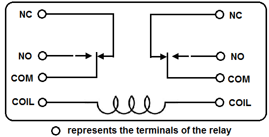
The 2 COIL terminals is where the voltage is placed in order to energize the coil. Place the relay's rated coil voltage on these terminals. The polarity of the voltage does not matter. A positive and negative voltage can be placed on either end. Polarity only matters if a diode is used.
The COM terminal is the common terminal. If the COIL terminals are energized with the rated voltage, the COM and the NO terminals have continuity. If the COIL terminals are not energized, then the COM and the NO terminals have no continuity.
The NC terminal is the Normally Closed terminal. It is the terminal that can be powered on even if the relay doesn't receive any or sufficient voltage to operate.
The NO terminal is the Normally Open terminal. It is the terminal where you place the output that you want on when the relay receives its rated voltage. If there is no
voltage to the COIL terminals or insufficient voltage,
the output is open and receives no voltage. When the COIL terminals receive the rated voltage or a little under, the NO terminal receives
sufficient voltage and can turn on the device on the output.
To find out the full information on wiring up a Double Pole Double Throw (DPDT) relay, check out
How to Connect a Double Pole Double Throw (DPDT) Relay to a Circuit.
Related Resources
How to Build a Relay Driver Circuit
Types of Relays
Relay Terminals
Relay Wiring Diagrams
SPST Relay Wiring Diagram
SPDT Relay Wiring Diagram
How to Connect a Single Pole Single Throw (SPST) Relay to a Circuit
How to Connect a Single Pole Double Throw (SPDT) Relay to a Circuit
How to Test a Relay
How to Test the Coil of a Relay
How to Test the Relay Contacts