
Filter Capacitor- Explained
A filter capacitor is a capacitor which filters out a certain frequency or range of frequencies from a circuit.
Usually capacitors filter out very low frequency signals. These are signals that are very close to 0Hz in frequency value. These are also referred to as DC signals.
How Filter Capacitors Work
How filter capacitors work is based on the principle of capacitive reactance. Capacitive reactance is how the impedance (or resistance) of a capacitor changes in regard to the frequency of the signal passing through it. Resistors are nonreactive devices. This means that resistors offer the same resistance to a signal, regardless of the signal's frequency. This means, for example, that a signal of 1Hz and a signal of 100KHZ, will pass through a resistor with the same resistance. Frequency isn't a factor. However, a capacitor is not like this. A capacitor is a reactive device. Its resistance, or impedance, will vary according to the frequency of the signal passing through. Capacitors are reactive devices which offer higher resistance to lower frequency signals and, conversely, lower resistance to higher frequency signals, according to the formula XC= 1/2πfc.
Being that a capacitor offers different impedance values to different frequency signals, it can act effectively as a resistor in a circuit. We will explain below how using actual circuits.
Filter Capacitor Circuit To Block DC and Pass AC
Being that capacitors have offer very high resistance to low frequency signals and low resistance to high frequency signals, it acts as a high pass filter, which is a filter which passes high frequency signals and blocks low frequency signals.
Many times in a circuit, both DC and AC signals need to be both be used in a circuit, at least at a certain stage of the circuit. However, at another stage, in the circuit, we may only want AC signals and the DC taken out. An example of such a circuit is a microphone circuit. We need DC as input to the microphone for it to be able to be powered on and we need AC as input, which represents the voice signal or music, etc. which we want the microphone to record.
How do we filter out the DC component of the signal?
We use a capacitor to filter out the DC signal.
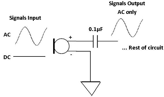
We do this by placing the capacitor in series. In this configuration, which is the circuit you see below, this is a capacitive high-pass filter. Low frequency, or DC, signals will be blocked.
Usually, a 0.1µF ceramic capacitor, or value around that range, is placed after the signal that contains both DC and AC
signals. And this capacitor filters out the DC component so that only AC goes through.
Filter Capacitor Circuit To Filter Out AC Signals
In the same way that capacitors can act as high-pass filters, to pass high frequencies and block DC, they can act as low-pass filters, to pass DC signals and block AC.
Instead of placing the capacitor in series with the component, the capacitor will be placed in parallel.
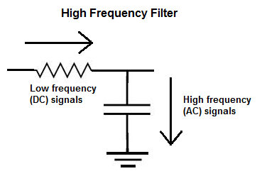
The above is a high-frequency capacitive filter. Remember that current takes the path of least resistance. Since a capacitor offers very low resistance
to high frequency signals, high frequency signals will go through the capacitor. In this way, with the circuit in this configuration, the circuit is a high frequency
filter. Low frequency current signals will not go through the capacitor, because it offers too much resistance to low frequency signals. Only high frequency signals
go through.
Filter Capacitor Experiment
To see how a capacitor acts as a filter, you can conduct an experiment with relative ease.
All you have to do is take a capacitor, any value or type, and hook it to a function generator. Then take an oscilloscope and connect it to the output of the capacitor.
For my experiment, I hooked up a 100nF (0.1µF) ceramic capacitor in series with a function generator to see which frequencies the capacitor blocked or attenuated and which frequencies went through unimpeded.
It turns out the capacitor blocked only very low frequency signals, between 0 Hz to about 0.5Hz, or
500 mHz. It will attenuate signals a little from about 0.5Hz to 3Hz. But after that, it no longer attenuates
signals above 3Hz. Signals 4Hz and above go through completely unimpeded, unblocked and unattenuated.
| Frequency | Signal Output |
| 0 Hz to 0.5Hz | Great amount of attenuation; Almost Completely Blocked |
| 0.5Hz to 3Hz | Some attenuation of the signal but not much |
| 3Hz and Above | Signal goes through completely unimpeded; No attenuation |
And you can perform the same test in parallel for a high frequency filter setup.
Related Resources
High Pass Filter
Low Pass Filter
Capacitor Charge (Charging) Calculator
Capacitor Impedance Calculator
Capacitor Equations
How to Calculate the Current Through a Capacitor
How to Calculate the Voltage Across a Capacitor