
High Pass Filter- Explained
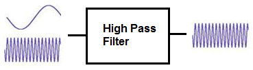
A high pass filter is a filter which passes high-frequency signals and blocks, or impedes, low-frequency signals.
In other words, high-frequency signals go through much easier and low-frequency signals have a much harder getting through, which is why it's a high pass filter.
High pass filters can be constructed using resistors with either capacitors or inductors. A high pass filter composed of a resistor and a capacitor is called a high pass RC filter. And a high pass filter with a resistor and an inductor is called a high pass RL filter.
We will go through both of these type of circuits on this page and show how both RC and LC high pass filters
are constructed. Both circuits have the effect of passing through high frequency signals while impeding low-frequency ones.
High Pass RC Filter
A high pass RC filter, again, is a filter which passes through high-frequency signals, composed of a resistor and capacitor.
To create a high pass RC filter, the capacitor is placed in series with the power signal entering the circuit, such as shown in the circuit
below:
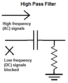
The above is a high pass filter. As a capacitor is a reactive device, it offers differing resistance to signals of different frequencies entering through it. A capacitor is a reactive device which offers very high resistance to low-frequency, or DC, signals. And low resistance to high-frequency signals. As it offers very high resistance to DC signals, it blocks them from entering through, as you can see in the circuit diagram above. So this type of filter only allows high-frequency signals to pass through and not DC. This type of capacitor also functions as a coupling capacitor because it couples the AC signal from one part of a circuit to another, while blocking the DC.
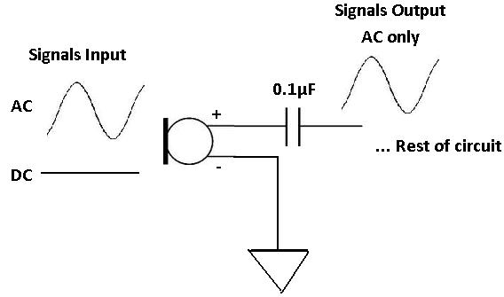
High pass filters are very common and are used in many type of circuit setups. One such circuit in which they are used are in microphone circuits. Microphones
are devices which need both DC and AC signals in order to work. Microphones need DC power in order to have the power to turn on and be able to operate. And they record
AC signals, such as human speech, music, noises. Thus, they deal with both type of signals. The DC is only needed to power the microphone on and should not appear
on the output with the AC signal. The DC is for power only and should not be mixed with the audio signal. So to pass the AC signal through and block the DC, we use
a high pass filter, so that only the AC signal appears on the output.
How to Build a RC High Pass Filter
Now that we've gone through what a high pass RC filter is, let's go over a practical example of building one.
To build a high pass filter, the components we will use are a function generator, a 10nF ceramic capacitor, and a 10KΩ Resistor.
This is the schematic of the circuit we will build, shown below:
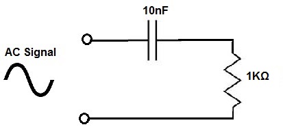
So the formula to calculate the frequency of an RC circuit is, frequency= 1/2πRC. Doing the math, we get, frequency= 1/2πRC= 1/2(3.14)(1000Ω)(0.00000001F)= 15,923 Hz.
Therefore, this RC circuit will pass frequencies above 15,923Hz with barely no attenuation. Frequencies below 15,923Hz will be attenuated. The further away and lower it is from 15,923Hz, the greater the output signal is attenuated.
So if we input an AC signal into the circuit from the function generator and place the signal to a very low frequency signal such as 100Hz or so, the capacitor will block out this voltage signal and it will not go through to output or be greatly attenuated. You can check this if you have an oscilloscope. If you now increase the frequency of the signal to 20KHz, the signal will go through unimpeded, not being blocked at all. The capacitor will have no effect and all high frequency signals pass through unimpeded without any attenuation.
This is a diagram below showing what happens to low and high frequencies when fed into this high pass filter:
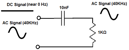
The low frequency signals (near 0 Hz) are blocked and do not go past the capacitor. Therefore, these signals do not show up on output.
The high frequency signals go through unimpeded and pass to output. This is why it's a high pass filter. It passes through high frequencies but block
low frequencies.
High Pass RL Filter
A high pass RL filter is a filter composed of a resistor and inductor which passes through high-frequency signals.
To build a high pass RL filter, the inductor is placed in parallel to the power source signals entering the circuit, as shown below in the following circuit:
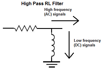
The above circuit is an RL high pass filter. It passes through high frequency signals. An inductor, like a capacitor, is a reactive device. Inductors offer different resistances to signals input into them of different frequencies. Inductors pass low-frequency signals with very little resistance, while offering great resistance to signals of high frequency. Thus, low-frequency signals pass through very easily without any attenuation and high frequency signals are either completely blocked or greatly attenuated as output.
Off of this principle described, which is
inductive reactance is how the above circuit operates. Remember that current in a circuit always takes the path of least resistance.
Since inductors offer such high resistance to high frequency signals, current signals of high frequency will not go through the inductor of this circuit. They
will take an alternate path and go through another part of the circuit which offers lesser resistance. In this circuit, instead of the high-frequency signals going through the inductor and
down to ground, they go through to output. And this is why this circuit is a high-pass filter circuit.
Low frequency signals, however, will go through the inductor, because inductors offer very low resistance to low-frequency, or Dc, signals. Therefore, low-frequency
current will take the path of going through the inductor to ground.
How to Build a High Pass RL Filter
To build a high pass RL filter, again, just like with the RC circuit, we use a function generator, a resistor, and an inductor. We use an oscillscope to check the signal.
For this circuit, we use a 470mH inductor and a 10KΩ resistor, with the following circuit configuration:
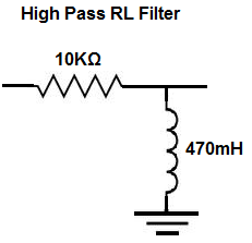
This circuit will form a high pass filter, passing through high frequency signals through to output, while filtering low-frequency signals through the inductor.
Since the formula for a high-pass RL filter is f= R/2πL, doing the math we get, f= R/2πL= 10KΩ/(2(3.14)(470mH))= 3,388 Hz, which
is approximately 3.39KHz.
This means all frequencies above 3.39KHz will be passed through without attentuation,
while frequencies below this value will begin to get attenuated. As you get lower and lower and further away from 3.39KHz,
there is greater attenuation as the frequency goes down.
To see how a high pass filter works in a real circuit, see the following video.
Below you can see a video of an RC high pass filter. This video demonstrates how the RC high pass
filter lets high-frequency signals pass through to
output with full gain, no attenuation, while greatly attenuating low-frequency signals.
Related Resources
High Pass Filter Calculator
Low Pass Filter
Low Pass Filter Calculator
Filter Capacitor
Capacitor Charge (Charging) Calculator
Capacitor Impedance Calculator
How to Calculate the Current Through a Capacitor
How to Calculate the Voltage Across a Capacitor