
How to Build a Half Adder Circuit
In this circuit, we will show how we can build a half adder circuit with an XOR and an AND gate chip.
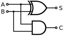
A half adder circuit is a circuit that adds 2 single binary digits togethers. It has 2 outputs, which are sum(S) and carry (C).
The sum represents the sum of the 2 binary digits. If both binary digits are 0, the sum is equal to 0. If one binary digits is 1 and the other is 0, the sum will be equal to 1. If both binary digits are 1, the sum will be 1 but then there will be a carry of 1.
The carry represents the carry bit. It is 0 in all cases except in the case where the 2 bits being added are both 1. In this case, the carry is 1 and the sum is 1.
The difference between a half adder and a full adder is that a full adder adds binary numbers and accounts for values carried in as well as out. A half adder does not account for a number carried in.
The total value of the sum of a half adder is equal to 2C+S.
We'll explain this more below.
In this circuit, we use a 4081 AND gate chip and a 4030 XOR gate.
Components Needed
- 4030 XOR Gate
- 4081 AND Gate
- 2 470Ω resistors
- 2 10KΩ resistors
- 2 Pushbuttons
- Green LED
- Yellow LED
The 4081 is a quad 2-input AND gate. It can be obtained cheaply at various online retailers. One site it can be obtained is Tayda Electronics at the following link: 4081 Quad 2-Input AND Gate Chip.
The datasheet can be found at the following link: 4081 AND gate datasheet.
The 4081 is a 14-pin chip. Its pinout is shown below.
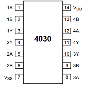
The 4030 is a quad 2-input XOR gate. It can be obtained cheaply at Tayda Electronics at the following link: 4030 Quad 2-Input XOR Gate Chip.
The datasheet can be found at the following link: 4030 XOR gate datasheet.
Just like the 4081, it is a 14-pin chip. Its pinout is shown below.
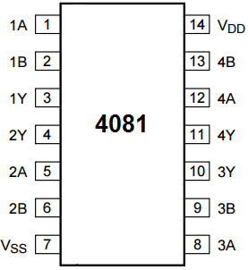
In both logic gate chips, the As and Bs are the inputs to the gates. The Ys represent the outputs of the gates.
With these logic chips, we will be able to construct a half adder, which is explained below.
Half Adder Explained
So a half adder is a circuit which adds 2 bits together. The bits are the augend and the added; these bits are labeled as A and B on the truth table below.
The half adder circuit has 2 outputs, the sum (S) and the carry (C).
Both the sum and the carry together give the full output. Neither, on their own, give the full output.
The output is decided by the formula, Sum= 2C+S.
So the total sum is equal to 2 times the carry + the sum.
So if the carry is 1 and the sum is 1, the total sum of the circuit is, 2C+S= 2(1)+1=3.
The reason this is the case is because the carry and the sum represent binary digits. The sum can be seen as the least significant binary digit and the carry can be seen as the most significant binary digit. The sum can be seen as the 20 place, which equals 1. And the carry can be seen as the 21 place, which equals 2. So if the sum is 1, it has a value of 1. And if the carry is 1, it has a value of 2.
The truth table showing the values of the outputs of the half adder is shown
below.
| Half Adder Truth Table | |||
| A | B | C | S |
| 0 | 0 | 0 | 0 |
| 1 | 0 | 0 | 1 |
| 0 | 1 | 0 | 1 |
| 1 | 1 | 1 | 1 |
Half Adder Circuit
The half adder circuit that we will build using a
4030 XOR gate chip and a 4081 AND gate chip is shown below.
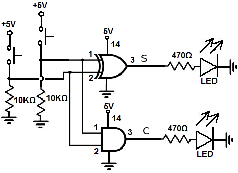
So we connect +5V of power to pin 14 on each of the logic chips and we connect pin 7
of the logic chips to ground. This establishes sufficient power to the chips.
We inputs to the 2 gates of each of the logic chips are pins 1 and 2. We tie the 2 logic pin 1s together and the 2 logic pin 2s togethers. We then put in a pull-down resistor to each of the inputs.
With pull-down resistors, when the pushbuttons are unpressed, the inputs will be at
a logic level of 0. When the pushbuttons are pressed down, the inputs go HIGH and now have a logic
level of 1.
How the Circuit Works
The circuit works based on the logic levels of the inputs.
The 2 inputs are the bits we want to add.
When the pushbuttons are unpressed, the inputs are at a logic state of 0 and when pressed are at a logic state of 1.
If we don't press down on any pushbuttons, the sum and carry bits will be LOW; so none of the LEDs will be ON.
If we press down on either one of the pushbuttons, the sum will be HIGH and have a value of 1. Therefore, the LED attached to the sum output will be ON.
If we press down on both pushbuttons, the sum and carry bits will be HIGH;
so both LEDs will be ON.
And this is how a half adder works.
Related Resources
How to Build an LED Flasher Circuit with a 555 Timer Chip
How to Build a Clock Circuit with a 555 timer
How to Build a 555 Timer Delay Before Turn On Circuit
How to Build a 555 Timer Delay Before Turn Off Circuit
How to Build a Sine Wave Generator with a 555 Timer Chip