
How to Build a Dark-activated Light Circuit Using an LM741 Op Amp
In this project, we will go over how to build an automatic night light circuit in which an LED will turn on automatically when it becomes dark using an LM741 op amp chip as a comparator.
As soon as there is ambient darkness sensed by the circuit, it will automatically turn on an LED, which will stay on as long as it is dark.
The component that allows for this light sensing is a photoresistor. The photoresistor detects light levels and its resistance changes based on the amount of light it picks up. We can exploit this varying resistance that the photoresistor gives off to know whether there is darkness in the surroundings or whether it is bright.
We will use the LM741 chip in this circuit as a comparator to make decisions. It was just explained how a photoresistor changes its resistance drastically based on the ambient lighting in an environment. Exposed to darkness, a photoresistor has a tremendous amount of resistance. Depending on the specific photoresistor in use, its resistance can be anywhere from over 100KΩ to well over 2MΩ. When exposed to bright light, a photoresistor's resistance drops drastically. Again, based on the photoresistor, it may be to 5KΩ or below or to about 30KΩ. For any photoresistor, you can pretty much be sure that the resistance will fall to about 30KΩ when exposed to bright light. This is an important principle to know because we will create a voltage divider composed up of a photoresistor and a fixed resistor, in which the voltage divided up between the 2 components will change due to ambient lighting. In darkness, the photoresistor will have a very high resistance. If you know ohm's law, more voltage is allocated to components with a higher resistance value (V= IR). Therefore, when this voltage divider is connected to a comparator, the voltage divider will produce a very high voltage. When the photoresistor is exposed to bright light, will have a low resistance. Therefore, less voltage will fall across it. So when it is hooked up to a comparator, the voltage divider circuit will produce a voltage less than the reference voltage. This will make more sense when you see the actual circuit.
So now you see how we can get varying voltage levels due to the varying resistance that a photoresistor gives off, based on the lighting in a room.
So how does the circuit actually make decisions due to the varying voltage levels?
And the answer is through a comparator.
A comparator is a electronic chip that can compare voltages between 2 inputs and whose output varies depending on which input has a greater voltage.
Look at the LM741 chip which we will use below:
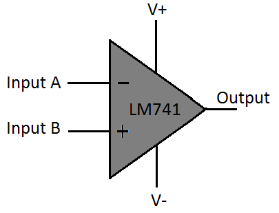
The LM741 basically has 2 inputs, input A, the inverting terminal (marked with a negative), and input B, the noninverting terminal (marked with the +).
If the voltage present on input B (the noninverting terminal) is greater than the voltage present on input A (the inverting terminal), then the output will be whatever is present on the V+ terminal of the LM741. This will be a positive voltage.
If the voltage present on input B (the noninverting terminal) is less than the voltage present on input A (the inverting terminal), then the output will be whatever voltage is present on the V- terminal of the LM741. The V- is usually tied to ground or to a negative voltage.
So assuming that the V+ terminal of the LM741 has a positive voltage (say 2.5V) and the V- terminal is tied to ground, when the photoresistor is exposed to darkness, a very large voltage from the power supply gets allocated to it. Thus, the voltage on the noninverting terminal is much larger than on the inverting terminal. Thus, the output will be pulled up to the voltage on V+. And, therefore, the load, which in this case is an LED, connected to the output terminal of the LM741, will be powered on.
If the photoresistor is exposed to bright light, its resistance drops signifcantly and so does its voltage. Thus, the inverting terminal will have a greater voltage than the noninverting, and the output of the LM741 will be drawn low, to ground. Thus, the LED will not light.
And this is the basis of our circuit.
In order to know how to build this circuit, you must know the pinout of an LM741, in order to connect the pins properly.
Below is the pinout of the LM741 op amp chip.
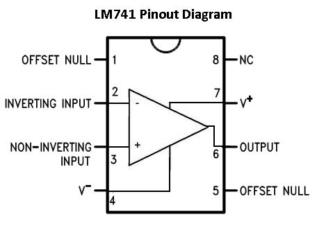
If you would like to understand all the pin connections of the LM741 op amp, see LM741 Op Amp- Pinout Connections. This article explains all of the 8 pins of the LM741 and what each one does.
For this circuit, though, we will only be connecting to 5 of the pins of the LM741.
As most ICs need power, we must power the chip. Therefore, we must connect positive voltage to the V+ terminal of the LM741 and connect either negative voltage to the V- terminal or connect it to ground. The supply voltage for the LM741 for the power voltage terminals can be as high as ± 22V. This means we can feed a voltage as high as +22V into V+ and as low as -22V to V-.
Besides for power, the 2 inputs that we will use to compare voltages are the inverting terminal and the noninverting terminal. These 2 terminals serve as inputs so that we can compare the voltages to determine which is higher.
The last pin we will use of the LM741 is the output pin. Here is where we connect the load that we want to power, in this case, it is
an LED. When the voltage on the noninverting terminal is greater than on the noninverting terminal, the output is high and the load will be powered on,
if the supply voltage is sufficient to
power on. If the voltage on the noninverting terminal is less than at the inverting terminal, the output is low and will be at the voltage level as V-.
Components Needed
- Photoresistor
- 33KΩ Resistor
- 330Ω Resistor
- 10KΩ Potentiometer
- LM741 op amp
- LED
- 3 AA batteries or DC Power Supply
A lot of these components can be varied somewhat. If your photoresistor's light resistance is about 20-30KΩ, then you definitely must use a resistance greater than 30kΩ. You must use a fixed resistor greater than the light resistance of the photoresistor to form the voltage divider. The resistor doesn't have to be 33KΩ. You can use a larger valued resistor, such as 40KΩ. It isn't precise.
The same is true for all the other resistors. The current-limiting resistor doesn't have to be exactly 330Ω,
it can be more or less but in the hundreds of ohms range. And the potentiometer
can really be any value. It isn't the value of the resistance of the potentiometer which is important, but the voltage that is produced when the potentiometer is calibrated to the right voltage.
We want the voltage of the potentiometer to be greater than the voltage that the voltage divider produces when exposed to bright light but less than the voltage that the voltage divider produces
when exposed to darkness.
Night Light Circuit Schematic
Below is the full schematic diagram of the circuit which we are building.
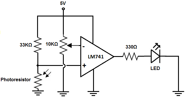
As you can see, the op amp is powered by 5 volts. The V+ terminal is connected to 5V and the V- terminal is connected to ground. The 2 inputs are the inverting and noninverting terminals. The voltage divider is connected to the noninverting terminal. This voltage will change depending on the ambient lighting. We adjust the potentiometer connected to the inverting terminal to the point where the LED is off during bright light exposure and on during darkness exposure.
Once this calibration is in place, the circuit is all set.
In bright light, the photoresistor has much less resistance than the 33KΩ resistor. Thus, most of the voltage falls across the 33KΩ resistor and not the photoresistor. In this case, the voltage at the noninverting terminal is much less than at the inverting terminal. The LED will be off.
In darkness, however, the photoresistor has much greater resistance than the 33KΩ resistor. Thus, most of the voltage falls across the photoresistor and not the 33KΩ resistor. In this case, the voltage at the noninverting terminal is greater than at the inverting terminal. The LED will be on.
So this is how a dark-activated light circuit can work.
This circuit is useful when light is needed during dark conditions, such as when night approaches.
Again, as always, variations of this circuit can be done. Instead of using an LED, we can use any other type of lighting
fixture such as a lamp. You may want to use a bright LED. Or you can use
any other various lighting source. You may want to use multiple lights, so you can place different lights in parallel in one another. All that would be needed
is an adjustment in the voltage and current of the circuit. Customize
the circuit according to your needs and preferences.
To see how this night light circuit works in real life, see the video below.
Related Resources
How to Build a Dark-activated Switch
How to Build a Hall Effect Sensor Circuit
How to Build a Touch Sensor Circuit
How to Build an Accelerometer Circuit
How to Build a Motion Detector Circuit
How to Build a Motion Detector Alarm Circuit