
How to Build a Light-activated Motor Circuit

In this project, we will go over how to build a light-activated motor circuit.
This is a circuit in which a motor will turn on and spin when there is adequate light in the ambient environment.
As soon as ambient light is sensed by the circuit, the motor will automatically turn on and remain on as long as the light remains.
The component that allows for the light sensing in this circuit is a photoresistor. The photoresistor detects light levels and its resistance changes based on the amount of light it picks up. We can exploit this varying resistance that the photoresistor gives off to know whether there is darkness in the surroundings or whether it is bright.
When it is exposed to darkness, a photoresistor has a tremendous amount of resistance. Depending on the specific photoresistor in use, its resistance can be anywhere from over 100KΩ to well over 2MΩ. When exposed to bright light, a photoresistor's resistance drops drastically. Again, based on the photoresistor, it may be to 5KΩ or below or to about 30KΩ. For any photoresistor, you can pretty much be sure that the resistance will fall to about 30KΩ when exposed to bright light. This is an important principle to know because we will connect our photoresistor in series to the base of a transistor. The type of photoresistor we will use will have a dark resistance greater than 2MΩ and a light resistance of around 30KΩ. This means when it is exposed to darkness, it will have a resistance greater than 2MΩ and when it is exposed to bright light, it will have a resistance of about 30KΩ.
Our photoresistor will be connected to the base of a transistor. When there is total darkness in the environment, the resistance of the photoresistor will very high. Therefore, inadequate current will flow through the base of the transistor, not sufficient enough to turn the transistor on. Therefore, no current will flow from the emitter and collector. However, when the photoresistor is exposed to bright light, its resistance drops dramatically to about 30KΩ. This resistance is low enough to cause a sufficient amount of current to flow through the base of a transistor to turn on the transistor. With the transistor now on due to the lowered resistance of the photoresistor, current can flow from the emitter to collector, powering on whatever load is connected to the collector, which in our case will be a DC motor.
And this is the basis of our circuit. The transistor provides current amplification of the base current so that
the amplified current is sufficient to drive a DC motor.
Components Needed
- GL5537 Photoresistor
- NPN BJT Transistor
- Diode
- 4 'AA' batteries or a DC power supply
- 3V DC Motor
The GL5537 photresistor has a dark resistance of 3MΩ and a light resistance of 30-50KΩ. This is perfect connection to the base of a transistor because 30-50KΩ allows for sufficient current to flow through the base to power on the transistor while a resistance of 3MΩ does not. This allows us to control on-off conditions of the transistor based on the ambient light or absence of it.
The NPN BJT that can be used can be a 2N3904 or a 2N2222.
The diode can be any such as from the 1N400X line.
A diode is placed in parallel, in reverse, to the DC motor. Motors, as well as relays, can
produce a very high back EMF voltage when they are turned off due to energy they store in the coils.
This excess voltage can damage the switching transistor. The diode shorts this back EMF out so that
the transistor and other electronic components in the circuit don't get damaged.
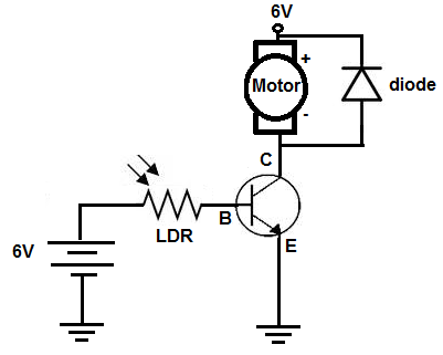
Light-activated Motor Circuit Schematic
The light-actived motor circuit we will build is shown below.
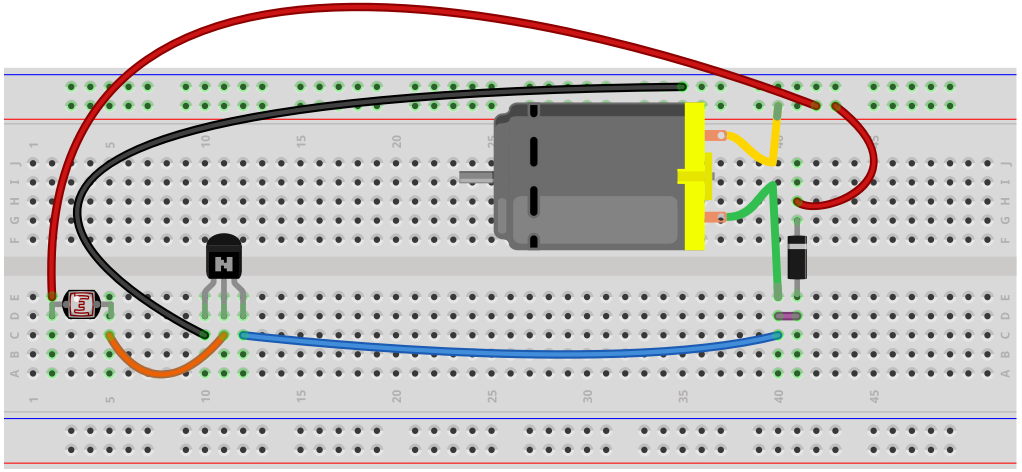
Below is the same circuit shown on a breadboard.
So this is the full schematic of the circuit.
Again, in darkness, the photoresistor's resistance will be so high, that barely any current flows through the base of the transistor. Thus, it does not turn on and allow current to flow from emitter to collector to power on the DC motor.
However, in bright light, its resistance falls dramatically and now sufficient current flows through the base of the transistor, turning the transistor on. Current now flows from the emitter to collector, powering on the DC motor.
And this is how a light-activated motor circuit can work.
To see how this light-activated motor circuit operates in real life, see the video below.
Related Resources
How to Build a Dark-activated Switch
How to Build a Hall Effect Sensor Circuit
How to Build a Touch Sensor Circuit
How to Build an Accelerometer Circuit
How to Build a Motion Detector Circuit
How to Build a Motion Detector Alarm Circuit