
Notch Filter Calculator
Narrowband Twin-T Notch Filter
The twin T notch filter calculator calculates the values of the resistors and capacitors needed to obtain a notch frequency as entered in by the user.
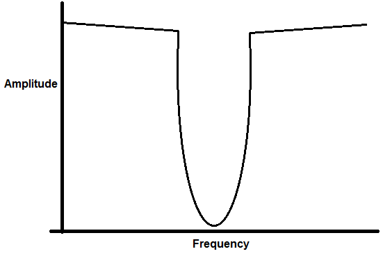
The notch frequency is the frequency that is most greatly attenuated by the circuit. So, if for example, a user enters a notch frequency of 4KHz, 4KHz is greatly attenuated by the circuit.
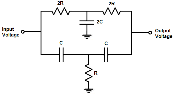
The reason the circuit is called twin T notch filter is that if you look at the circuit diagram, two 'T's are formed that are identical in shape, which is why they are called twins.
Each of the Ts forms a filter. The top T filter forms a low pass filter. The low pass filter is composed of 2 resistors and 1 capacitor. The bottom T filter forms a high pass filter. The high pass filter is composed of 2 capacitors and 1 resistor.
Notice that the filters are in parallel. They are able to form a notch filter, or bandstop filter, because of the fact that they are in parallel. The low pass filter allows frequencies below the cutoff point to pass through and the high pass filter allows frequencies above its cutoff point to pass through. All the frequencies that can't pass through (or passes through with great attenuation) are in between these points. The point of maximum attenuation occurs at the notch frequency.
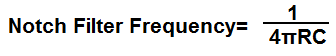
The formula for calculating the notch frequency is, notch frequency= 1/4πRC, where π equals 3.14, R is the resistance, and C is the capacitance.
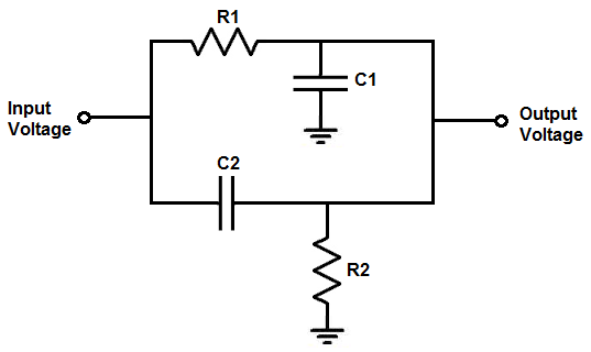
Also worth pointing out is that the maximum value of the output voltage below the notch frequency is less than the maximum value of the output voltage above the notch frequency. The reason for this is that the series resistances (2R1) in the low pass filter provide greater circuit losses than the series capacitors (C1) in the high pass filter.
To use this calculator, a user simply enters in the notch frequency desired and the calculator will compute all the values of the resistors and capacitors.
This calculator has a significantly more narrowband than the circuit following that can be used for wideband filter applications.
Wideband Notch Filter
This wideband notch filter calculator calculates the values of the resistors and capacitors based on the notch frequency range entered and the amount of attenuation that is desired at the output.
Unlike the twin-T notch filter, this wideband notch filter can have a much larger range for the bandstop.
To use this calculator, a user enters the lower frequency and the upper frequency. The lower frequency is where the user wants the bandstop to start and the upper frequency is where the user wants the bandstop to end. So, for example, if you want the bandstop to be active from 1KHz to 10KHz, 1KHz is the lower frequency and 10KHz is the upper frequency.
The next important part of this calculator is that you specify the amount of attenuation that is desired at the start and stop points of the bandpass filter. The different attenuation values are -15dB, -20dB, -30dB, -40dB, -50dB, and -60dB.
-15dB means that the voltage is 0.177 of the input peak voltage. This means that if 1V is fed into the input of the circuit, the output voltage at the beginning and end points of the notch filter will be 0.177 the peak voltage. This is equal to an output voltage that is 17.7% the signal strength of hte input voltage. So it provides an attenuation of 82.3%.
-20dB is even lower. As you get higher negative values, the attenuation is greater. -20dB means the voltage is 0.1 of the input peak voltage, or 10% of the input peak voltage. This means there is an attenuation of 90%.
-30dB means that the voltage is 0.0316 the peak voltage. This is equal to an output voltage that is 3.16% of the input voltage. This means that there is an attenuation of 96.84%.
-40dB means that the voltage is 0.01 the peak voltage. This is equal to an output voltage that is 1% of the input voltage. This means that there is an attenuation of 99%.
-50dB means that the voltage is 0.00316 the peak voltage. This is equal to an output voltage that is 0.316% of the input voltage. This means that htere is an attenauation of 99.684%.
-60dB means that the voltage is 0.001 the peak voltage. This is equal to an output voltage that is 0.1% of the input voltage. This means that there is an attenuation of 99.9%.
So you choose the level of attenuation that you desire for the lower and upper cutoff frequencies. Of course in between the 2 frequencies, there is even greater attenuation, but you choose the level of attenuation that is acceptable for those 2 frequencies.
How the formulas are derived are based on the fact that the frequency response of the low pass filter drops 20dB per decade after the -3dB cutoff point. So if you do the math, the frequency drops 2dB for each 0.1 of a decade. So, for example, at the -5dB point, the frequency has dropped to 9KHz if the -3dB cutoff point was 10KHz. So the calculator calculates the dB value based on this principle.
For the high pass filter, the same principle applies. A high pass filter drops 20dB per decade, but from right to left instead of a low pass filter dropping from left to right.
What is meant by per decade is taking the -3dB frequency and multiplying it by 10 (for a low pass filter) or dividing by 10 (for a high pass filter). This comprises one decade. So if the -3dB cutoff point is 10KHz, a decade spans to 100KHz for a low pass filter or 1KHz for a high pass filter. During this span, there is a drop in 20dB. If you take it another decade, this would span to 1MHz for a low pass filter or 100Hz for a high pass filter. So each decade (multiplying the frequency by 10 or dividing by 10), there is a drop in 20dB.
Just like the twin-T notch filter, the wideband notch filter has the low pass filter and the high
pass filter in parallel with each other. When they are in parallel, the voltage output can go to output from either
of 2 paths. It can go to output either from the high pass filter or the low pass filter. If the voltage is at
the low pass frequency cutoff point or lower, it will pass through to output either at peak voltage or 0.707V
the peak voltage. If the voltage is at the high pass frequency cutoff point or higher, it will pass through
to output either at peak voltage or 0.707V the peak voltage. All frequencies in between these points are attenuated
less than 0.707 times the peak voltage. By choosing the level of attenuation desired, you can choose the amount
of attenuation you want at the lower and upper cutoff frequencies. The frequencies in between these points will
be attenuated even more.
Related Resources
Low Pass Filter Calculator
High Pass Filter Calculator
Bandpass Filter Calculator
Center Frequency Calculator
Quality Factor Calculator
Colpitts Oscillator Calculator
Hartley Oscillator Calculator