
Quality Factor Calculator

The quality factor (Q-factor) calculator calculates the quality factor of either a bandpass filter circuit or a notch filter circuit.
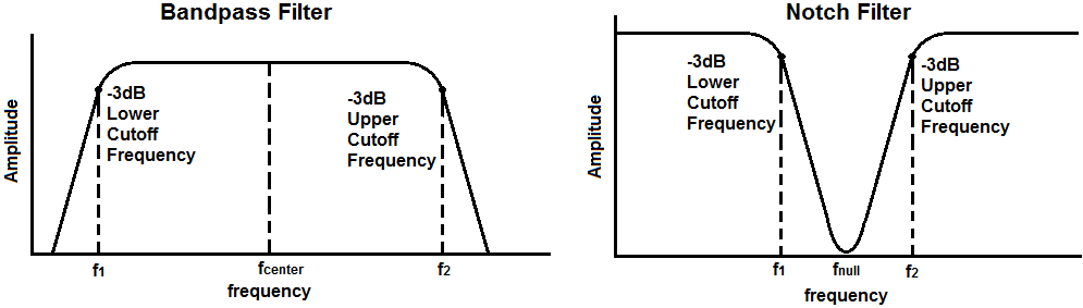
For a band pass filter, the quality factor is the ratio of the center frequency of the bandpass over the entire bandpass region from the lower to upper cutoff frequencies. Therefore, for a bandpass filter, the quality factor, Q= fcenter/ (f2 - f1).
The frequencies, f11 and f2, are the 2 -3dB cutoff frequencies. F1 is the lower cutoff -3dB frequency and f2 is the upper -3dB cutoff frequency.
The center frequency is the frequency in the center point of the bandpass. The center frequency,
fcenter= √
However, for narrowband filters, where the ratio of f2 to f1 is less than 1.1, the response shape approaches arithmetic symmetry and we can approximate the center frequency to be, fcenter= (f1 + f2)/2
So these formulas above are how we can calculate the center frequency to find the Q-factor.
A high quality factor indicates the bandpass is narrow. For example, let's assume that a bandpass filter circuit has a bandpass from 2KHz to 3KHz. Using the formula, we get Q-factor of 2.5. Since the bandpass filter is very narrow, the difference between f2 and f1 is small. Therefore, the denominator is relatively small, making for a large Q-factor.
A low quality factor indicates the bandpass is wide. For example, let's assume that a bandpass filter circuit has a bandpass from 1KHz to 50KHz. Using the formula, we get a Q-factor of 0.144. Since the bandpass is very wide, the difference between f2 and f1 is large. Therefore, the denominator is relatively large, making for a small Q-factor.
So Q-factor, again, is the ratio between the center frequency over the difference between the 2 -3dB cutoff frequencies. It gives a good metric of how narrow or wide the bandpass is for a given bandpass circuit design. Certain bandpass filter designs only allow for narrowband bandpasses, or high Q-factors. Others allow for much wider bandpasses, or low Q-factors.
For a notch filter circuit, the quality factor is defined as the ratio of the entire stopband from f2 to f1 over the center frequency of the stopband, which is referred to as the null frequency or notch frequency. .
So, for a notch filter, the quality factor is the entire stopband from the -3dB cutoff points over the null frequency, where the attenuation is the greatest. The quality factor shows how narrow or wide the stopband is for a notch filter.
The quality factor of a notch filter is, Q= (f2 - f1)/fcenter.
The center frequency is the center frequency of the stopband for a notch filter. It is the also referred to as the null frequency or the notch frequency.
The center frequency is determined just as before with the bandpass filter.
The center frequency,
fcenter= √
However, for narrowband filters, where the ratio of f2 to f1 is less than 1.1, the response shape approaches arithmetic symmetry and we can approximate the center frequency to be, fcenter= (f1 + f2)/2
The frequencies, f1 and f2 are the 2 cutoff -3dB frequencies.
A high quality factor for a notch filter indicates the stopband is narrow. For example, let's assume that a notch filter circuit has a stopband from 2KHz to 3KHz. Using the formula, we get Q-factor of 2.5. Since the stopband is very narrow, the difference between f2 and f1 is small. Therefore, the denominator is relatively small, making for a large Q-factor.
A low quality factor indicates the stopband is wide. For example, let's assume that a notch filter circuit has a stopband from 1KHz to 50KHz. Using the formula, we get a Q-factor of 0.144. Since the stopband is very wide, the difference between f2 and f1 is large. Therefore, the denominator is relatively large, making for a small Q-factor.
So the quality factor again for a notch filter is the difference between the -3dB cutoff frequencies over the null frequency. It gives a good metric of how narrow or wide the stopband is for a given notch filter circuit design. Certain notch filter designs only allow for narrowband stopbands, or high Q-factors. Others allow for much wider stopbands, or low Q-factors.
To use this calculator, a user simply enters the values of the 2 cutoff frequencies and specify whether the filter is a bandpass filter or a notch (bandstop) filter.
The resultant q factor is then calculated and displayed.
Related Resources
Low Pass Filter Calculator
High Pass Filter Calculator
Bandpass Filter Calculator
Notch Filter Calculator