
How to Build a Simple Tilt Sensor Circuit

In this project, we will go over how we can use a tilt sensor in a circuit.
A tilt sensor is a sensor that can allow us to detect the orientation or inclination of a circuit.
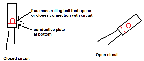
Tilt sensors work by having a free moving mass, usually a rolling ball, in them with a conductive plate beneath. When the sensor is completely upright, the ball falls to the bottom of the sensor, touching the electrical connection path, closing the electrical connection from the 2 end terminals, allowing current to be able to flow. When the sensor is tilted, the ball does not fall to the bottom and close the electrical conductive path. Therefore, the conductive path is open and no current can flow.
Below illustrates the concept of how the tilt sensor works:
So we can use this concept of how tilt sensors work to build a useful circuit. If the circuit is completely upright, the tilt sensor forms a closed electrical path and allows current to flow and power a device. If the device is tilted, the circuit will become open and will no longer conduct current that can power a load. So, in other words, the electronic device shuts off once it is tilted from its upright orientation.
This is very useful for electronic devices that can be a safety hazard if it tilts or falls from its upright position. A prime example of a device that normally has this feature are heaters. A heater is a device that can produce a tremendous amount of heat energy. Being that it can, it can be a serious potential fire hazard. Thus, we do not want the device to be tilted from its upright position at all. If it is, it might fall on something else, while producing tremendous heat and spark a fire. By putting a tilt sensor in the circuit, we can shut off the heater if it is kicked or turned over from its normal upright orientation.
Although there are other ways of implementing safety shutoff when a circuit is tilted from normal orientation, a tilt sensor is one of the ways this can be implemented.
A tilt sensor is sometimes referred to as the "poor man's accelerometer" but this is not really an accurate
depiction. Although both devices measure tilt and inclination, a tilt sensor is different in that it does not need a
microcontroller in order to interpret its data. It's a standalone. It's a much simpler device. An accelerometer needs a microcontroller
to interpret its X and Y-axis readings to see how tilted it is. A tilt sensor acts more like a switch. It's either open or
closed and will either close or open electrical connection in a circuit. It does not give specific or advanced readings, but
at the same time, it does not need a microcontroller to interpret its data. It's a simpler version that gives switch-like results
but not a poor version because at times this simplicity is wanted rather than the more advanced data that an accelerometer
will give.
Components Needed
- Tilt Sensor
- 470Ω Resistor (if using LED)
- LED or other load
- DC Voltage Source
A tilt sensor can be bought for a cheap price ($2.00) from Adafruit- Tilt Ball Switch.
All we need other than that is a load. In this case, we will use an LED. But in actuality, you can use any load. Just know the voltage that the load will need in order to power on.
The DC voltage source can be from any source, including batteries, a DC power supply, or a wall wart.
Tilt Sensor Circuit
A basic circuit that uses a tilt sensor is shown below:
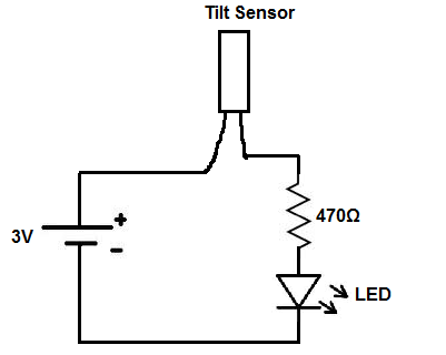
This tilt sensor circuit again is very basic. When the device has power and is in its upright position, the free rolling ball will settle at the bottom, forming electrical connection. The LED will then receive sufficient current and power o. If the circuit gets tilted so that the ball now does not settle at the bottom with the electrical conduction path, the circuit now becomes open. Being that the path is broken, current can no longer flow through and the LED does not receive current any longer. It therefore shuts off when the device is tilted beyond a certain degree.
Again, although, there are many ways to implement safety shutoff mechanisms if a device is turned over, a tilt sensor is one of the ways it can be done.
If you don't have a DC fan, change it for whatever load you have, just making sure the power you supply the circuit with is sufficient to drive that load. Experiment.
See the video below of the tilt sensor circuit which we've built:
In this circuit, if the tilt sensor detects tilt, the circuit simply shuts off. If you want to build a tilt sensor where
an alarm goes off if the circuit is tilted, see How to Build
a Tilt Alarm Circuit.
Related Resources
How to Build a Hall Effect Sensor Circuit
How to Build a Touch Sensor Circuit
How to Build an Accelerometer Circuit
How to Build a Motion Detector Circuit
How to Build a Motion Detector Alarm Circuit