
How to Build a D flip flop Circuit with a 4013 Chip
In this circuit, we show how to build a D flip flop circuit with a 4013 D flip flop chip.
A D flip flop is just a type of flip flop that changes output values according to the input at 3 pins: the data input, the set input, and the reset input.
All flip flops do the same thing- they store a value at the output(s) indefinitely unless the value is intentionally changed by manipulating the inputs. If we don't change the input values, then the values at the outputs stay the same.
The 4013 is a dual D flip flop chip. This means it's composed of 2 independent flip flops. However, in this circuit, we will simply show how to operate 1 of them. If you know how to use 1 of them and how it works, then you will know how to use the other one.
In this circuit, we will operate the flip flop using nothing but manual pushbutton control.
By using pushbuttons to control the inputs, you can see exactly how the flip flop reacts to changes in inputs .
You can physically how the output changes.
Therefore, it's very hands-on and you can really see how a D flip flop operates according to its logic truth table.
Components Needed
- 4013 Dual D Flip Flop Chip
- 3 Pushbuttons
- 3 1KΩ Resistor
- 2 470Ω Resistor
- Red LED
- Green LED
An 4013 dual D flip flop is a 16-pin chip.
It can be obtained very cheaply at a number of online electronic retailers. It can be obtained at Tayda Electronics at the following link: 4013 Dual D Flip Flop.
The pinout is shown below:
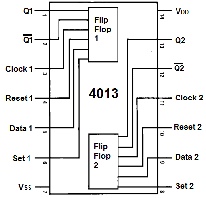
To power the 4013 D flip flop chip, we feed 5V to VDD, pin 16 and we connect VSS to ground. This establishes sufficient power to the chip. The 4013 can actually take a wide range of voltage, anywhere from 3V-15V.
The 4013 is composed of 2 independent flip flops, labeled on the input as flip flop 1 and flip flop 2.
Each flip flop has 6 pins attached to it.
The clock pin is the pin where we feed a clock signal. The 4013 executes instructions on the rising edge of a clock signal.
Pin 5 is the data pin. It outputs a data value of either 0 or 1 from the flip flop.
Pin 4 is the reset pin. If the reset pin alone is HIGH (while the set pin is LOW), this resets the Q
and
Pin 6 is the set pin. If the set pin alone is HIGH (while the reset is LOW), this sets the Q pin to 1
and the
The 2 output pins are Q and
This gives a description of each of the pins of the chip.
The 3 input pins are the data, set, and reset pins. The values to these pins dictate the value of the
output pins, Q and
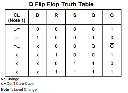
Below is the truth table for the D flip flop pulled from the datasheet of the 4013 chip.
The output values, Q and
4013 D Flip Flop Circuit
The schematic diagram of the 4013 D flip flop is shown below.
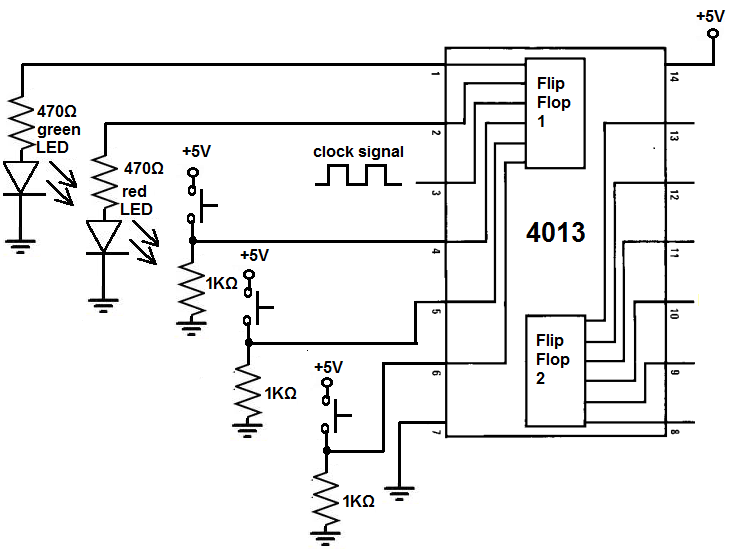
To power the 4013, we feed 5V to VDD, pin 16 and we connect VSS, pin 8, to ground.
We connect a clock signal to the clock of the 4013, which is pin 3. This clock pin can be obtained from a number of sources such as a frequency generator. Or a 555 timer chip. Or a 4046 chip. It can even be obtained from a 7414 schmitt trigger inverter chip.
We connect each of the 3 input pins, the data pin, set pin, and reset pin to a pull-down resistor. So normally when the pushbutton is not pressed, the pin will be in a LOW state. When we push down on the pushbutton, this now brings it to a HIGH state. So initially all the pins have a value of 0 but when we push down on the pushbutton, it then has a value of 1.
We connect the 2 output pins to LEDs. To the Q output pin, we connect a green LED. And to the
How the Circuit Works
This circuits through manual pushbutton control. We have 3 pushbuttons connected to the 3 inputs of the flip
flop chip. These inputs change the values of the output pins, Q and
X on the truth table means that the value of that pin doesn't matter. You can see mostly for the D or data input. It means it doesn't matter what logic state the data input is in.
If the set pin is 0 and the reset pin is 0, while the D pin is 0, then the Q output is 0 and the
If the set pin is 0 and the reset pin is 0, while the D pin is X, then the Q output and the
If the set pin is 0 and the reset pin is 0, while the D pin is 1, then the Q output is 1 and the
If the set pin is 1 and the reset pin is 0 (D is X), then the Q output is 1 and the
If the set pin is 0 and the reset pin is 1 (D is X), then the Q output is 0 and the
If the set pin is 1 and the reset pin is 1 (D is X), then the Q output and the
Flop flops have many applications. They can be used in toggle circuits. Since the Q and
Other applications include data terminals, alarm systems, and computers. Computers contain millions of flip
flops. Flip flops are the basis of registers in computers. And there are a lot of registers in a computer. Flips are used in
memory devices. Because they store bits, they form the basis of memory, computer storage.
Related Resources
How to Use the LM741 Op Amp as a Comparator
How to Build an LM339 Quad Voltage Comparator Circuit
How to Build a Dark-activated Switch
How to Build a Hall Effect Sensor Circuit
How to Build a Touch Sensor Circuit
How to Build an Accelerometer Circuit
How to Build a Motion Detector Circuit
How to Build a Motion Detector Alarm Circuit