
How to Build an LM339 Quad Voltage Comparator Circuit
We will go over how to build a quad voltage comparator circuit using an LM339.
The LM339 is a quad op amp comparator.
This means it is made up of 4 independent op amps.
This means that up to 4 different input values can be compared.
A comparator works by a simple concept. Each op amp of a comparator has 2 inputs, a inverting input and a noninverting input. If the inverting input voltage is greater than the noninverting input, then the output is drawn to ground. If the noninverting input voltage is greater, then then the output is drawn high to VCC. So if the output of an op amp is attached to an LED, the LED will turn on if the voltage at the inverting terminal is greater than the voltage at the noninverting terminal. And the LED will be off when the voltage at the noninverting terminal is greater than at the inverting terminal.
With an LM339, since it has 4 op amps (it is a quad op amp comparator), an engineer can use the 4 op amps
to compare 4 values. The output will be drawn high to Vcc for those op amps that have a greater inverting voltage than noninverting
voltage. And the output will be drawn to GND for those op amps that have a greater noninverting voltage than inverting.
LM339 Pinout
The pinout for the LM339 op amp is shown below:
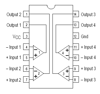
The pinout is very straightforward.
The 4 op amps each have 3 pins. They have 2 inputs to compare input is greater. And they have an output whose voltage is dependent on the comparison of the 2 inputs. If the inverting voltage is greater, the output will drawn high to Vcc. If the noninverting voltage is greater, then the output will be drawn low to GND. This applies to each of the 4 op amps. If each of the op amps have inverting voltages greater than noninverting voltages, then all of the outputs will be drawn high to Vcc. If all the noninverting voltages are higher, the outputs will all be drawn down to GND.
Aside from the inputs and outputs of the op amps, the LM393 has 2 pins for power. One pin is Vcc, where the positive voltage connects to and the other is GND, where either gets hooked up to GND or negative voltage. This serves a dual purpose. This gives the LM393 power so that the chip can work. And secondly, the voltage that is fed into these power pins serve as circuit biasing. The amount of voltage fed to the power pins gets applied to the output pins to power whatever loads are connected to the output terminals of the op amps. Therefore, enough power must be fed to the power pins of the op amp in order to power whatever loads are attached to the output terminals of the chip. This means if you are powering a 9V motor, at least 9V must be fed into the power pin of the LM393.
So to demonstrate the LM393, we will build a circuit that will show how it works.
Components Needed
- LM339 Op Amp Comparator IC
- 4 Potentiometers
- 4 330Ω Resistors
- 4 LEDs
- 4 'AA' batteries or DC power supply
The potentiometers can really be of any value. It doesn't matter.
If you are using batteries to power the circuit, then you can just use a single 'AA' battery (which is 1.5V) in place of the +2V. And you can use 3 'AA' batteries to produce
4.5V instead of the 5V. Even if you used only 2 'AA' batteries for 3 volts, the circuit will still power on and work.
LM339 Quad Voltage Comparator Circuit Schematic
The circuit schematic for the LM339 quad voltage comparator circuit that we are going to build is shown below.
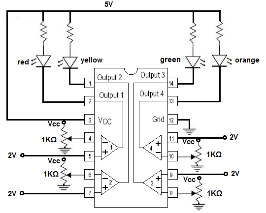
This circuit is really built for demonstration purposes, just so to show you how to connect an LM339 and how it works.
In this circuit, there are 4 different color LEDs, so that we can demonstrate each of the 4 op amps one at a time.
To each of the inverting terminals of the op amps, we connect the wiper terminal of a potentiometer. One end of the potentiometer goes to Vcc and the other end goes to ground.
To each of the noninverting terminals of the op amps, we connect +2V of power.
For powering the LM339 chip, we connect the Vcc terminal (pin 3) of the chip to +5V and we connect the GND terminal (pin 12) to ground. This gives the LM339 the power it needs to operate as well as provide biasing for our circuit. This is because when the inverting terminal is greater than the noninverting terminal for an op amp, the output will be brought to Vcc.
To each of the output pins, we connect a current-limiting resistor (about 330Ω) and an LED. The LEDs are all different colors, but if you don't have all the different colors, using the same color is fine. It will still work the same. The colors serve to distinguish the different outputs but if you use the same colors, you can still easily observe how this circuits.
With all pins connected up, we can now go over the circuit works. And it's very basic.
First, before we demonstrate the circuit, adjust all the potentiometers so that they output near 0Ω of resistance. This will make sure that all the outputs are off when we first operate the circuit. If you power on the circuit now, all the LEDs should be off. Now take your potentiometer adjuster and adjust the potentiometer so that its resistance increases. When you turn it at some point, the point where it goes above 2V, the first LED will light up. This is because now the inverting terminal voltage is greater than noninverting terminal voltage. Thus, the output swings from VCC to ground, and the load gets powered on. If we repeat this for the next 3 op amps (adjusting the potentiometer), the same result will occur. Each of the output LEDs will light up when the voltage goes above the reference 2V fed into the noninverting terminal.
And this demonstrates how an LM339 chip can be connected to function as a quad voltage comparator.
To see how this circuit works in real life, please see the video below.
Related Resources
How to Use the LM741 Op Amp as a Comparator
How to Build a Comparator Circuit with an LM311
How to Build a Comparator Circuit with an LM393
How to Build a Dark-activated Switch
How to Build a Hall Effect Sensor Circuit
How to Build a Touch Sensor Circuit
How to Build an Accelerometer Circuit
How to Build a Motion Detector Circuit
How to Build a Motion Detector Alarm Circuit