How to Build a Liquid Level Sensor Circuit with an AVR
In this project, we will build a liquid level sensor circuit with an AVR chip.
This circuit will be able to tell us how much of the sensor is covered in liquid.
Liquid level sensors are used for all types of applications in which any type of fluid or liquid needs to be measured or monitored. They are extensively used within automobiles, which rely on a substantial amount of different fluids in order to operate to check for how much gas in the car, windshield washer fluid, oil levels. But outside of automobiles, they are used just as extensively. Thus, they are extremely valuable to be able to learn and manipulate and build circuits with.
The liquid level sensor we will use is an analog sensor, meaning it outputs an analog voltage in proportion to the amount of liquid the sensor is exposed to. We just connect the analog pin, represented by an S, to an analog pin on the AVR chip, so that the analog voltage it outputs can be read.
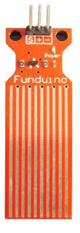
As you can see from the above image, the sensor has a series of parallel wires across the board. These wires are what sense the liquid level that the board is exposed to. If the board has water or another fluid covering all the wire, then it will output a maximum analog value reading. If no liquid is covering it, then it will read a near 0 value. And if it is partially submerged, the value will be between 0 and maximum.
With our liquid level sensor and an AVR chip, there are a number of circuits we can build. We can use the sensor, simply, to read and output the analog value obtained. Or we can create a type of alarm indicator status system, such as have an LED light up if the liquid level goes below the 1/4 level, like how car dashboard LED indicators tell us when our gas tank goes below E (empty). We can also have an LED light up if the sensor is completely submerged, indicating it's full. Or we can have a circuit with 2 LEDs, one that indicates when it's full and one that indicates when it's empty.
So with a microchip like the AVR, there are basically limitless options of how we can use the liquid level sensor.
In this circuit, we will build now, we will just do the most basic circuit and simply read and output
the analog value
read by the AVR.
Components Needed
- Atmega328/168 Chip
- Liquid Level Sensor
- 0.1μF ceramic capacitor
- AVR Programmer
The AVR chip we will use is either the Atmega168 or Atmega328 chip. Both have the same pin layouts. If you need a reference for the pinout of the AVR chip to gain more familiarity with what each pin does, see Atmega328 Pinout. You'll need to be familiar with what each pin does in order to really know how to connect up this circuit meaningfully.
The liquid level sensor we will use is built by China Harbin Okumatsu Robot Technology Co and its product item is RB-02S048. This part can easily be obtained on ebay for most of the time under $2 including shipping. It's very inexpensive.
The sensor operates on 5V and needs less than 20mA for operating power current, which means the arduino can easily provide this (so no external power is needed to power it).
The liquid level sensor has 3 pins. It's very basic. The pinout is shown below.
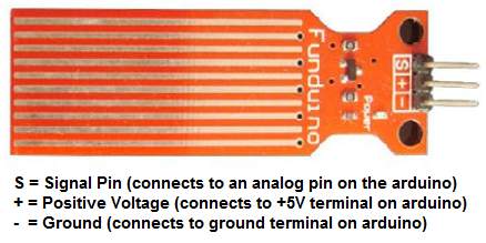
2 of the pins are for power, 1 connecting to +5V and the other connecting to ground.
The other pin, with an S, is the signal pin. This is the pin that outputs the analog voltage signal in proportion
to the amount of liquid immersing
the sensor. This pin connects to an analog pin of the AVR. The AVR has 6 analog pins, PC0 to PC5. So it must go into one of these 6 pins.
For our circuit, we will connect it to analog pin PC0 (pin 23).
AVR Liquid Level Sensor Circuit
The schematic diagram of the AVR liquid level sensor circuit is shown below.
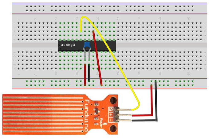
The first thing is the liquid level sensor and the AVR both need power in order to operate. So they are both connected to the +5V power line and to ground.
The signal pin (S) of the liquid level sensor gets connected to an analog pin on the arduino board. Here we connect it to analog pin PC0 (pin 23). This allows the AVR chip to be able to read the analog voltage value.
The only other connection we make in our hardware circuit schematic is tying AVCC to VCC. AVCC is the power supply for the analog-to-digital converter inside the AVR chip. Without its own power supply, the ADC can't function. It needs its own power source in order to operate. Therefore, we must connect it to VCC for the ADC to work. Without it, we won't be able to measure analog signals because the ADC is necessary to convert the analog signal to a digital signal, which is the only type of signal that the AVR can interpret. Therefore, you can see why tying it to AVCC is the only way an analog circuit can work.
The reason we don't have to ground the ground wire of the ADC is because both grounds on the AVR chip. So being that one GND terminal is already connected to ground, we don't have to ground the ADC ground.
And the reason we don't have to tie AREF to anything is because in our software, we connect make it so that AVCC and AREF are internally
connected. Therefore, AREF will be AVCC.
Code
With the hardware setup, all we need now is the code to obtain the sensor reading.
The code for the AVR potentiometer circuit is shown below.
#include <avr/io.h>
#include <util/delay.h>
#include <stdio.h>
static inline void initADC0(void) {
ADMUX |= (1 << REFS0);
ADCSRA |= (1 << ADPS1) | (1 << ADPS0);
ADCSRA |= (1 << ADEN);
}
int main(void) {
uint16_t liquidsensor_value;
initADC0();
while (1) {
ADCSRA |= (1 << ADSC);
loop_until_bit_is_clear(ADCSRA, ADSC);
liquidsensor_value= ADC;
printf ("Liquid Level: %i\n", liquidsensor_value);
return (0);
}
}
So we first import libraries to our files. This is because this libraries contain definitions or functions we use in our code.
Next, we write code for the initialization of our ADC. We set the reference voltage to AVCC, we set the ADC clock prescaler to 1/8 of the clock speed, and we enable the ADC. All of this ADC initialization is done in code.
Next, we create 2 16-bit variables, photoresistorValue and threshold_level. Since the ADC is 10-bit ADC, meaning it holds 10 value places, the variable to hold this
10-bit ADC value must be in a 16-bit register, not an 8-bit register. We then initialize the threshold_level to 716. This is because we will set the threshold level to be 3.5V. If the voltage is below
3.5V, this means the photoresistor is exposed to sufficient lighting, and the LED should not turn on. If the voltage is above 3.5V, then it is exposed to dark lighting conditions. 3.5V is 70% or
0.7 of the 5V supplying the voltage divider circuit. Being that a voltage of 0V translates into an ADC value of 0 and a voltage of 5V translates into an ADC value of 1023, a voltage of 3.5V will
translate into an ADC value of 716 (0.7 * 1023= 716). Therefore, 716 is our ADC threshold value. This is a binary value of 0b1011001100. If below this level, the LED will be off. If above this level,
the LED will turn on. And this is basically how the AVR night light circuit works.
Related Resources
How to Use the LM741 Op Amp as a Comparator
How to Build an LM339 Quad Voltage Comparator Circuit
How to Build a Dark-activated Switch
How to Build a Hall Effect Sensor Circuit
How to Build a Touch Sensor Circuit
How to Build an Accelerometer Circuit
How to Build a Motion Detector Circuit
How to Build a Motion Detector Alarm Circuit