
How to Build a 2-Axis Thumb Joystick Circuit with an Arduino
In this project, we will show how to connect a thumb joystick to an arduino board.
The type of thumb joystick we will connect in this project is a 2-axis joystick, which means it can record movement in 2 directions, top to bottom and left to right, or horizontal and vertical movement.
Thumb joysticks are cool and can be implemented for a variety of circuits, the main chief use being for video game or arcade controllers. They are used in countless video game controllers, including nintendo 64, playstation 2, playstation 3, game cube, xbox, xbox 360, and wii controllers. They're pretty much standardized with all video game controllers. You will see them greatly also on arcade machines, if you were to visit an arcade.
Being that they are used for such cool video game consoles, we will go over how we can connect our own to an
arduino so that
Components Needed
- 2-axis Thumb Joystick
- Arduino
The 2-axis thumb joystick can be obtained easily from ebay, as there are normally auctions for it in the $4-$5 range. Just type in "2-axis thumb joystick arduino" to get a joystick which is compatible with the arduino.
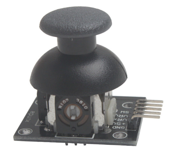
The pinout of the 2-axis thumb joystick that will be specifically used for this circuit is shown below.
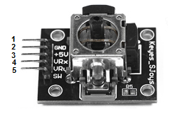
This serves as a good reference for what the board should look like and what its pinout should be.
The first pin is GND. This connects to the power supply ground or negative terminal.
The second pin is +5V. This connects to positive 5V in order to power on the joystick.
The third pin is VRx. This gives a readout of the joystick in the horizontal direction, how far left and right the joystick is pushed, the X-coordinate.
The fourth pin is VRy. This gives a readout of the joystick in the vertical direction, how far up or down the joystick is pushed, the Y-coordinate.
The fifth and last pin is SW. It is a digital swtich which allows us a select option. When the joystick knob
is pressed down, this is when the knob, in whatever position it is in, is pressed. This is the equivalent with us selecting
the knob position. When the SW switch is connected to a digital pin of the arduino, it can read digitally whether the
joystick knob has been pressed down, signaling a select, or not.
Arduino 2-Axis Thumb Joystick Circuit Schematic
The 2-axis thumb joystick circuit we will build is shown below.
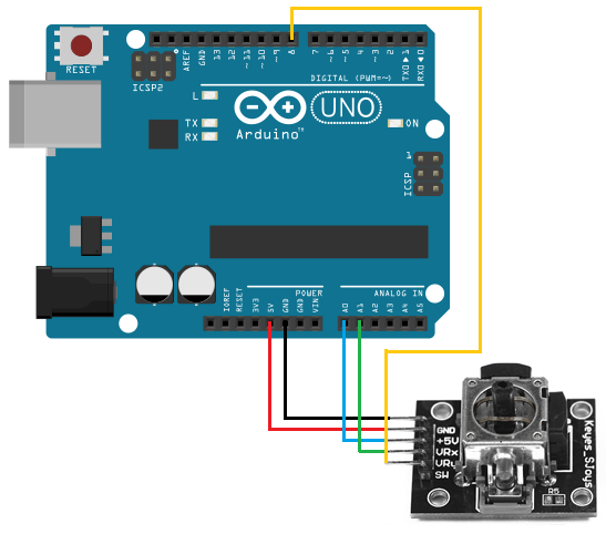
To determine the X and Y coordinates of the joystick, we need two analog reading pins on the arduino. Since the coordinates are analog signals output by the joystick, they require connection to analog pins in order to be read. For our arduino board, we connect VRx to analog pin A0 of the arduino and we connect VRy to analog pin A1 of the arduino. Now, with this hardware setup, we can read the coordinates from the joystick.
To read whether the joystick knob has been pressed down, which means the user is trying to select a particular configuration of the joystick, we connect the SW pin of the joystick to digital pin D8 of the arduino. If we don't press down on the joystick knob, the digital readout from the SW pin will be HIGH. If HIGH, it means it is unpressed and, thus, unselected. If pressed down, the digital readout will then be LOW, meaning it is pressed. Thus, with this switch, we can actually know if a user is selecting a particular configuration of the joystick.
Other than this, the joystick just simply needs power. Its 5V pin is connected to the 5V terminal of the arduino
and its GND pin is connected to the GND terminal of the arduino.
Code
The code for our 2-axis thumb joystick circuit is shown below.
const int VRxPin= 0;
const int VRyPin= 1;
const int SwButtonPin= 8;
int pressed= -1;
int x= -1;
int y= -1;
void readJoystick() {
pressed= digitalRead(SwButtonPin);
x= analogRead(VRxPin);
y= analogRead(VRyPin);
}
void setup() {
pinMode(SwButtonPin, INPUT);
digitalWrite(SwButtonPin, HIGH);
Serial.begin(115200);
}
void loop() {
readJoystick();
Serial.print("X: ");
Serial.println(x);
Serial.print("Y: ");
Serial.println(y);
Serial.print (" Pressed: ");
Serial.println(pressed);
delay(10);
}
The first block of code establishes the connections of the joystick pins to the arduino. Since the VRx pin connects to analog pin A0, it is initialized to 0. Since the VRy pin connects to analog pin A1, it is initialized to 1. Since the SW pin connects to digital pin D8, it is initialized to 8.
The second block of code creates variables which hold the value of the various pins of the joystick. The first variables, pressed, will hold the value if the knob joystick has been pressed down or not. The variable, x, will hold the value of the X-coordinate of the joystick, its horizontal defelction. The variable, y, will hold the value of the Y-coordinate of the joystick, its vertical deflection.
The next block of code creates the function readJoystick(). This function reads the value of the SW pin, VRx, and the VRy pin using either the digitalRead() function for the SW pin or the analogRead() function for the VRx and VRy pins.
The next block of create is our setup() function. This establishes the SW pin as input and puts it HIGH. This is because when the SW pin is HIGH, it means it is not pressed. This is the default value we want for the joystick circuit. When the user presses down on the joystick knob, this signals a press and the SW pin goes down to LOW, connecting to ground. This is when it is pushed down on. Also in this block of code, we set the baude rate to 115200.
The next block of code is the loop(), which executes over and over and over again in an infinite loop. Therefore, it calls the readJoystick() function every 10 milliseconds and gets
a new X-coordinate and Y-coordinate. It also checks constantly to see if the knob is pressed down.
And this is how a 2-axis thumb joystick with an arduino operates.
Related Resources
How to Use the LM741 Op Amp as a Comparator
How to Build an LM339 Quad Voltage Comparator Circuit
How to Build a Dark-activated Switch
How to Build a Hall Effect Sensor Circuit
How to Build a Touch Sensor Circuit
How to Build an Accelerometer Circuit
How to Build a Motion Detector Circuit
How to Build a Motion Detector Alarm Circuit