How to Build a Heat Detector Circuit Using an Arduino
In this project, we will go over how to build a heat detector circuit using an Arduino.
A heat detector circuit is a circuit, of course, which can detect the presence or absence of heat.
This could be useful for a wide range of circuits including any device that needs monitoring and protection from excess heat. When excess heat is given to a circuit, maybe this could be dangerous for the circuit. Thus, if too much heat is detected, we can make it so that an alarm, either light or sound, is triggered, telling us that the circuit is being exposed to a dangerous amout of heat.
In our circuit for this project, when a certain threshold is heat is reached, an LED will turn on, alerting us to this situation.
The device we will build in this project will be automatic in nature. As soon as the heat reaches a certain threshold, the LED attached to our arduino board will turn on right away, automatically.
For this project, the main component we will use is a thermistor. A thermistor's resistance varies based on the amount of heat that it is exposed to. In room temperature, an NTC (negative temperature coefficient) thermistor will have a resistance near its rated resistance value. So, for example, a 100KΩ thermistor will have near 100KΩ of resistance. However, if the thermistor is exposed to heat, its resistance will drop significantly, to below 40KΩ. We can exploit its varying resistance properties to determine if our circuit is being exposed to a high level of heat or if it isn't. If the thermistor's resistance is very high, it is exposed to a low level of heat. If it is very low, it is exposed to a high level of heat.
When we place a thermistor in series with a resistor, a voltage divider is formed. Voltage will be allocated to the 2 components based on the each one's respective resistance. More voltage will fall across the component with the greater resistance, according to ohm's law, V=IR. This is the principle in this circuit we exploit to determine the heat level that our circuit is exposed to and this will determine whether our LED turns on or off.
Components Needed for the Heat Detector Circuit
- 100KΩ NTC Thermistor
- 20KΩ Resistor
- Arduino
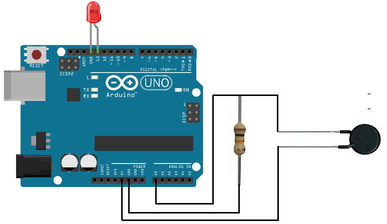
Heat Detector Circuit Schematic
The schematic for the heat detector cirucit is shown below:
Code
The code to turn on an LED when the heat detector level rises above a certain threshold is shown below.
const int ledPin=13;
const int sensorPin= 0;
int level;
const int threshold=700;
void setup() {
pinMode (ledPin, OUTPUT);
Serial.begin(9600);
}
void loop(){
level= analogRead(sensorPin);
if (level < threshold){
digitalWrite(ledPin, HIGH);
}
else{
digitalWrite(ledPin, LOW);
}
}
Here in this code, we first define the pin connections. Since the LED is connected to digital pin D13, we set the pin to 13. Since the sensorPin representing the thermistor voltage divider is connected to analog pin A0, we set it equal to 0.
Next, we declare an integer named level. This will represent the heat level of our circuit, meaning how much heat the circuit is exposed to. We also declare a variable named threshold and set it equal to 700. We later have code that if the circuit's heat level is less than the threshold, the LED will turn on.
The next line declares the ledPin as a digital output.
After this, the next block of code reads the value from the analog pin A0. If the heat level is below the threshold, the LED will light up.
The biggest part of all of this is knowing how the voltage divider circuit works. The voltage divider is again formed between the thermistor and the 20KΩ resistor. The total voltage that the arduino puts out is 5V. This 5V gets divided up between the thermistor and the 20KΩ resistor. When exposed to room temperature, the thermistor has a resistance of near 100KΩ. This means that most of the 5 volts will fall across the thermistor, approximately 0.83% of it, since 100KΩ/120KΩ= 0.83. This means that approximately 5V * 0.83= 4.17V of the 5V that the arduino outputs will fall across the thermistor during room temperature. The arduino analogRead() function works by reading the analog value that is output from the thermistor voltage divider circuit. The value output will range from 0 to 1023. If a full 5 volts falls across the thermistor, the analogRead() function will have a value of 1023. Since the thermistor shares the voltage with the 20KΩ resistor, it will n not have a full value of 1023. As stated before, it will be 0.83 of the 5V. So it will output an analogRead() value of about 850, since 1023 * 0.83≈ 850.
However, when the thermistor is exposed to high heat, well above 100°F, the thermistor's resistance falls dramatically, below 40KΩ. In this situation, the voltage that will fall across the thermistor will now be below 3.33V, since 40KΩ/60KΩ= 0.66. 5V * 0.66= 3.33V. The analogRead() function will output a value of approximately 675, since 1023 * 0.66≈ 675. Thus, you can now see why we set our threshold at 700. And you can see that if our analogRead() value falls below 700, this is a sign that the thermistor has been exposed to a high amount of heat. The LED will turn on, triggering a signal that there is a heat overload.
And this is how an automatic heat detector circuit can be built with an arduino.
Related Resources
How to Drive a 7 Segment LED Display with an Arduno
How to Build a Dark-activated Light Circuit
How to Build a Hall Effect Sensor Circuit
How to Build a Touch Sensor Circuit
How to Build an Accelerometer Circuit
How to Build a Motion Detector Circuit
How to Build a Motion Detector Alarm Circuit