Arduino Light Meter Circuit
In this project, we will go over how to connect an analog volt panel meter to an arduino so that it can measure and give us a readout of light striking the circuit.
In this way, the circuit will function as a light meter.
When there is a lot of light shining on the circuit, the meter will deflect greatly. When there is a low level of light hitting the circuit, the meter needle will barely deflect. In this way, we have a device that deflects based on the light level hitting it.
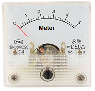
The type of analog panel meter we will use is really generic. Light is usually measured in unit lumens, lux, or candela. However, it will be very difficult to find an panel meter that is calibrated in terms of lumens, lux, or candela. So a generic panel meter can be used that is calibrated in volts. If the circuit is set up properly, the idea is that you can still see how much the needle swings in proportion to changes in light, even if an exact value can't be read. If the needle barely moves at all, it is exposed to either darkness or very small amount of light. If the needle swings about midway, it's exposed to a decent level of light. If the needle swings all the way left, bright light is being shone on it.
This way, we can demonstrate how to build a light meter.
For this circuit to work, the component that will be used to detect and measure the amount of light is a photoresistor. A photoresistor is a type of
special resistor whose resistance changes in proportion to the amount of light exposed to it. When exposed to darkness, it offers a great amount of resistance. Depending
on the type, it can be megohms of resistance. When exposed to bright light, its resistance drops drastically. Again, depending on the type it may fall below
30KΩ. We will build a voltage divider circuit so that we place a photoresistor in series with a fixed resistor. Since the photoresistor changes its resistance in
response to light and changed resistance incurs changed voltage, we can measure the amount of voltage the photoresistor has and know
whether it is exposed to a bright light
(low resistance) or darkness (high resistance). If the photoresistor is exposed to darkness, it will have a very high resistance. Thus, in a voltage divider circuit,
most of the voltage will fall across the photoresistor and not the fixed resistor. Thus, we will write our code so that under this condition, the needle does not deflect much.
If the photoresistor is exposed to bright light, it will have very low resistance, much less than that of the fixed resistor. Thus, most of the voltage will fall
across the fixed resistor and very little across the photoresistor. Under this condition, we write our code so that the needle deflects far right.
Components Needed for the Arduino Light Meter Circuit
- Analog Panel Meter
- 100KΩ Resistor
- GL5537 Photoresistor
The analog panel volt meter we will use can be found at Sparkfun here: Analog Panel Meter- 0-5VDC. This can measure from 0V to 5V of DC voltage with 2.5% accuracy. It's fairly accurate. This volt meter can play the role as our light meter for this circuit.
The GL5537 photoresistor comes in GL5537-1 and GL 5537-2. Both are acceptable to use for this circuit. The GL5537-1 has a dark resistance of 2MΩ and a light resistance of 20-30KΩ. The GL5537-2 has a dark resistance of 3MΩ and a light resistance of 3-50KΩ. Any photoresistor can be used that can has similar specs.
We want our photoresistor to have a dark resistance much higher than the fixed resistance and a light resistance much lower than the fixed resistance,
to provide a contrast in the voltage divider circuit. Since our fixed resistor will be 100KΩ, the GL5537 will work great with this fixed resistor for this purpose.
Arduino Light Meter Circuit Schematic
The arduino light meter circuit we will build is shown below.
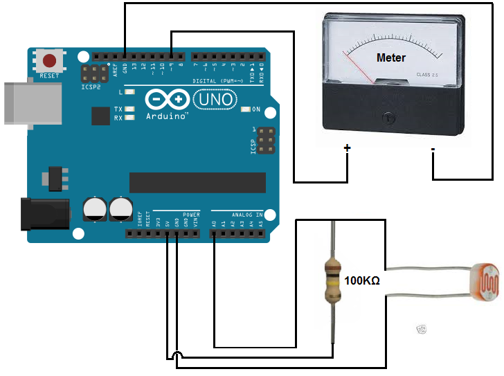
The circuit connections are pretty straightforward and basic.
When connecting the analog volt panel meter to the arduino, we connect one terminal to D9 of the arduino and the other terminal to ground (GND).
We connect the photoresistor and the fixed resistor in series. This forms a voltage divider circuit, because voltage divides up in series circuits.
The voltage will fall divide up based on the resistance offered by the components in series. More voltage will fall across components with greater resistance.
How our circuit will work is that when exposed to darkness, the photoresistor will have very high resistance. Thus, most of the 5V supplied by the 5V terminal will
fall across the photoresistor during dark lighting conditions. We will write code so that when the voltage is high across the photoresistor, the panel meter gauge
will deflect very little if at all, indicating there is very little to practically no light. When the photoresistor is exposed to bright light, its resistance is very
low; thus, the voltage that falls across it is very low. We will write code so that when the voltage is low across the photoresistor, the panel meter needle will deflect
greatly to the right, indicating bright lighting conditions. And this is how the circuit works.
Code
Now that we have our circuit schematic setup, the only thing we now need is our code so that the arduino will know to process the voltage that falls across the photoresistor, which is connected to analog pin A0, and then correspondingly allow for deflections of the panel meter.
The full code is shown below.
const int analogInPin= 0;
const int analogMeterPin= 9;
int sensorValue= 0;
int outputValue= 0;
int invertedValue;
void setup ()
{
//nothing in setup
}
void loop()
{
sensorValue= analogRead(analogInPin);
invertedValue= 1024 - sensorValue;
outputValue= map (invertedValue, 0, 1023, 0, 255);
analogWrite (analogMeterPin, outputValue);
}
Since the potentiometer wiper terminal is connected to analog pin A0, we initialize the constant analogInPin to 0. Since one terminal of the panel meter is connected to D9, we initialize the variable analogMeterPin to 9.
We later create a variable sensorValue which will hold the value of the voltage that falls across
the potentiometer and another variable invertedValue which serves as the value we send to the panel meter so that it knows how far to deflect the needle.
We then take another variable outputValue which takes the invertedValue, which can range from 0 to 1023,
and converts it into an analog value that ranges from 0 to 255. Once we have this converted value, we then can write this
value to the analog panel meter, which is connected to D9. This allows the meter to shift correspondingly with the
voltage drops across analog pin A0.
To see how this circuit works when actually connected together, see the video below.
Related Resources
How to Drive a 7 Segment LED Display with an Arduno
How to Build a Dark-activated Light Circuit
How to Build a Hall Effect Sensor Circuit
How to Build a Touch Sensor Circuit
How to Build an Accelerometer Circuit
How to Build a Motion Detector Circuit
How to Build a Motion Detector Alarm Circuit