How to Build a Liquid Level Gauge Circuit with an Arduino
In this project, we will build a liquid level gauge circuit with an arduino.
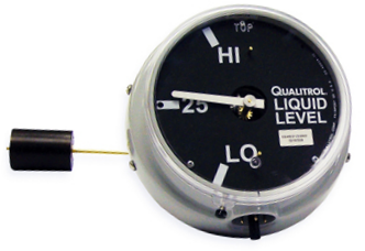
This is a circuit in which a liquid level can be monitored through a gauge.
We read the liquid level from the gauge (low, medium, or high), just as you see above.
With a microcontroller such as the arduino, building this circuit is a pretty simple feat.
The microcontroller can read the analog voltage from the liquid level sensor and then based on that value, we can send a proportional analog signal to the meter so that it can display to us the liquid level determined by the sensor.
Liquid levels can numerous applications, for whenever any type of liquids need to be measured and/or monitored.
Components Needed
- Arduino
- Liquid Level Sensor
- Analog Meter
The liquid level sensor we will use is built by China Harbin Okumatsu Robot Technology Co and its product item is RB-02S048. This part can easily be obtained on ebay for most of the time under $2 including shipping. It's very inexpensive.
The sensor is an analog sensor, meaning it outputs an analog voltage in proportion to the amount of liquid it is exposed to. The sensor has a series of parallel wires across the board. These wires are what sense the liquid level that the board is exposed to. We simply connect the analog pin, represented by an S, to an analog pin on the arduino board to read the analog value.
The sensor operates on 5V and needs less than 20mA for operating power current, which means the arduino can easily provide this (so no external power is needed to power it).
The liquid level sensor has 3 pins. It's very basic. The pinout is shown below.
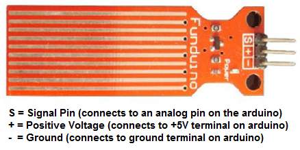
2 of the pins are for power, 1 connecting to the +5V of the arduino and the other connecting to the ground terminal of the arduino. The other pin, with an S, is the signal pin. This is the pin that outputs the analog voltage signal in proportion to the amount of the sensor which is covered with liquid. This pin connects to an analog pin on the arduino board to be read.
The analog panel meter we will use can be found at Sparkfun here:
Analog Panel Meter. The panel has a voltage display, as it is meant to be a voltmeter. But it will deflect perfectly fine, as if it were a panel meter for a liquid level sensor.The reason
I say to go with this panel is you won't really find a specific panel for liquid level sensors, unless you build your own or have it custom ordered, which may be extreme. Therefore, you can just
use the panel meter provided by Sparkfun. But if you're really serious, you can look.
This can measure from 0V to 5V of DC voltage with 2.5% accuracy. It's fairly accurate. When tested with a DC power supply, the
corresponding DC voltages were pretty much dead-on with what it should be.
Arduino Liquid Level Gauge Circuit
The schematic diagram of the arduino liquid level gauge circuit is shown below.
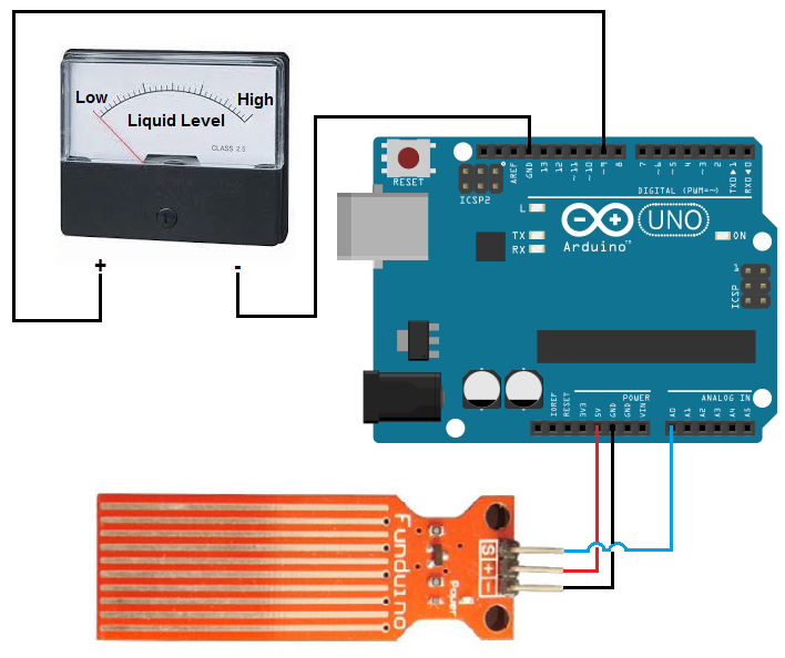
The connections are simple.
The liquid level sensor board needs about 5V of power, so they can to the arduino 5V and ground terminals.
The signal pin (S) gets connected to an analog pin on the arduino board. Here we connect it to analog pin A0. This allows the arduino board to be able to read the analog voltage value.
The LED we will light has its anode terminal connected to digital pin D13 and its cathode
Code
With the hardware setup, all we need now is the code to obtain the sensor reading.
const int sensorPin= 0;
const int analogMeterPin= 9;
int liquid_level;
int outputValue;
void setup() {
Serial.begin(9600);
pinMode(sensorPin, INPUT);
pinMode(analogMeterPin, OUTPUT);
}
void loop() {
liquid_level= analogRead(sensorPin);
Serial.println(liquid_level);
delay(100);
outputValue= map (liquid_level, 0, 1023, 0, 255);
analogWrite (analogMeterPin, outputValue);
}
In the first block of code, we declare the sensorPin variable and initialize it to 0, since it's connected to analog pin A0. We declare the analogMeterPin and initialize it to 9, since it's connected to digital pin D9. We then declare a liquid_level variable, which will hold the value of the analog value output from the sensor, serving as our sensor reading, which represents the liquid level. The outputValue variable will hold the value that we have to send to the panel meter for it to show a corresponding value in proportion to the sensor reading.
In our setup() function, we set the baud rate and make the sensorPin input, since it is an input value into the arduino board to be read. The analogMeterPin is an output.
In our loop() function, which is the code that repeats over and over, we read the value from the sensorPin and store it in the variable liquid_level. We then output this value to the Serial Monitor to be read just for debugging purposes. The code is constantly running this code over and over, so it obtains new readings endlessly. We give a delay of 100ms in between each reading to create a small pause in between.
The analogRead() function reads the sensor pin and returns a value anywhere from 0 to 1023 in proportion to the voltage from the sensor. If the sensor is submerged in no liquid
at all, the arduino will register a 0 reading. If the sensor is fully submerged in liquid, it will register a full reading of 1023. The analogWrite() function, however, that we need so that
the analog signal obtained from the liquid level sensor is transferred to the panel meter ranges anywhere from 0 to 255. Therefore, we use the map() function to convert the 0-1023 scale of the
analogRead() function to the 0-255 scale of the analogWrite() function. Once this is done, we call the analogWrite() function and send it this converted value. This value represents the proportional
analog value which ranges from 0 to 255. Thus, the needle of the panel meter will deflect correspondingly according to the level of the liquid the sensor is exposed to.
Related Resources
How to Use the LM741 Op Amp as a Comparator
How to Build an LM339 Quad Voltage Comparator Circuit
How to Build a Dark-activated Switch
How to Build a Hall Effect Sensor Circuit
How to Build a Touch Sensor Circuit
How to Build an Accelerometer Circuit
How to Build a Motion Detector Circuit
How to Build a Motion Detector Alarm Circuit