How to Build a Liquid Level Indicator Circuit with an Arduino
In this project, we will build a liquid level indicator circuit with an arduino.
This circuit will be able to indicate to a user when liquid levels fall below a certain level.
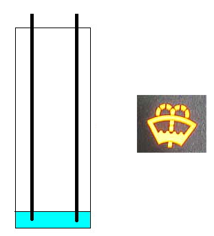
The circuit we will build is similar to what is on a vehicle dashboard for various fluids such as gas or windshield washer fluid. Once the gas gets near or below E (for empty), an LED will light up, indicating us to the fact that gas is low. The same thing occurs for windhshield washer fluid for a lot of cars.
A liquid level indicator circuit, thus, is a very valuable circuit. It is used extensively for all types of liquids for automobiles, as well as various other products in which liquid monitoring needs to take place.
For this circuit, we will light an LED when the liquid level that the sensor is exposed to falls below the quarter (1/4) mark, just as on a dashboard, an LED gets lit. Again, you can swap this out for any other indicator component such as a buzzer or vibrator, as long as the arduino can power it.
Technically, for our circuit, the liquid level indicator can be for when the circuit level falls below a
certain
level, as what we are doing now, or for when it rises above a certain level. It is just a matter of changing the less-than sign
to a greater-than sign in the code. This is easily modifiable, and it will be shown how to do so in the code section.
Components Needed
- Arduino
- Liquid Level Sensor
- LED
The liquid level sensor we will use is built by China Harbin Okumatsu Robot Technology Co and its product item is RB-02S048. This part can easily be obtained on ebay for most of the time under $2 including shipping. It's very inexpensive.
The sensor is an analog sensor, meaning it outputs an analog voltage in proportion to the amount of liquid it is exposed to. The sensor has a series of parallel wires across the board. These wires are what sense the liquid level that the board is exposed to. We simply connect the analog pin, represented by an S, to an analog pin on the arduino board to read the analog value.
The sensor operates on 5V and needs less than 20mA for operating power current, which means the arduino can easily provide this (so no external power is needed to power it).
The liquid level sensor has 3 pins. It's very basic. The pinout is shown below.
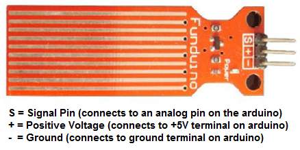
2 of the pins are for power, 1 connecting to the +5V of the arduino and the other connecting to the ground
terminal of the arduino.
The other pin, with an S, is the signal pin. This is the pin that outputs the analog voltage signal in proportion
to the amount of
the sensor which is covered with liquid. This pin connects to an analog pin on the arduino board to be read.
Arduino Liquid Level Indicator Circuit
The schematic diagram of the arduino liquid level indicator circuit is shown below.
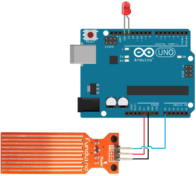
The connections are simple.
The liquid level sensor board needs about 5V of power, so they can to the arduino 5V and ground terminals.
The signal pin (S) gets connected to an analog pin on the arduino board. Here we connect it to analog pin A0. This allows the arduino board to be able to read the analog voltage value.
The LED we will light has its anode terminal connected to digital pin D13 and its cathode
Code
With the hardware setup, all we need now is the code to obtain the sensor reading.
const int sensorPin= 0;
const int ledPin= 13;
int liquid_level;
void setup() {
Serial.begin(9600);
pinMode(sensorPin, INPUT);
pinMode(ledPin, OUTPUT);
}
void loop() {
liquid_level= analogRead(sensorPin);
Serial.println(liquid_level);
delay(100);
if (liquid_level < 256){
digitalWrite(ledPin, HIGH);
}
else {
digitalWrite(ledPin, LOW);
}
}
In the first block of code, we declare the sensorPin variable and initialize it to 0, since it's connected to analog pin A0. We then declare the ledPin and initialize it to 13, since it's connected to digital pin D13. We then declare a liquid_level variable, which will hold the value of the analog value output from the sensor, serving as our sensor reading, which represents the liquid level.
In our setup() function, we set the baud rate and make the sensorPin input, since it is an input value into the arduino board to be read.
In our loop() function, which is the code that repeats over and over, we read the value from the sensorPin and store it in the variable liquid_level. We then output this value to the Serial Monitor to be read just for debugging purposes. The code is constantly running this code over and over, so it obtains new readings endlessly. We give a delay of 100ms in between each reading to create a small pause in between.
The analogRead() function reads the sensor pin and outputs a value anywhere from 0 to 1023 in proportion to the voltage from the sensor. If the sensor is submerged in no liquid at all, the arduino will register a 0 reading. If the sensor is fully submerged in liquid, it will register a full reading of 1023. The quarter mark would be 1023/4, which is about 256. Thus, when the reading falls below 256, then the liquid submerging the sensor has fallen below the quarter mark. When this occurs, the LED will be turned on, indicating us to this. Otherwise, the LED is off.
If you want to modify the circuit so that the LED turns on when the level rises above a certain level, to systems that need to monitor too much fluid buildup, then the only modification that needs to be done is in the code. The less-than sign simply is changed into a greater-than sign. Now, it will be that when the value is greater than a certain level, the LED will be turned on. The same thing applies if you want to check to see if the sensor is fully submerged in fluid, which for a gas tank would mean it's a completely full tank. Maybe for this situation, you would want to light a separate dash light, for a "FULL" light, such as a green LED. You could make code, such as if (liquid_level > 1000){ digitalWrite(greenLED, HIGH)}.
And, of course, as stated, you can swap out an LED for any other indicator you may want to use, such a buzzer or sirens.
And this is how a liquid level indicator circuit can be made with an arduino.
Related Resources
How to Use the LM741 Op Amp as a Comparator
How to Build an LM339 Quad Voltage Comparator Circuit
How to Build a Dark-activated Switch
How to Build a Hall Effect Sensor Circuit
How to Build a Touch Sensor Circuit
How to Build an Accelerometer Circuit
How to Build a Motion Detector Circuit
How to Build a Motion Detector Alarm Circuit