
How to Connect a Microphone to an Arduino
In this project, we will go over how to connect a microphone to an arduino so that the arduino can detect whether there is sound in the environment or not.
This circuit is only capable of detecting whether there is sound in the environment or not.
It won't be able to record the words that you say, with the ability of being able to play it back. Or do things such as record music or play it back.
The microphone simply serves to detect whether there is sound. The arduino also has the capability of measuring the level of the sound, so that only sounds above a certain threshold can a certain circuit action (if desired).
An application of using a microphone with an arduino is if you want to build some type of sound alarm circuit, in which sound triggers a circuit event such as flashing sirens or turning on a buzzer. For example, if you have a room that should be very quiet and someone breaks into it, making a lot of noise, a microphone placed in an arduino can easily trigger another electronic component. Another application could be a clap-on-off circuit, in which clapping can turn the circuit on or off.
Basically, any circuit that needs to be triggered by sound can be done with a microphone as input into an arduino.
How this circuit works is through the use of a microphone. We will use a microphone to be able to detect sound. But a microphone alone is insufficient for this circuit. This is because a microphone alone, without an amplifier, produces very small electrical signals. If we connected the output sound signals from a microphone directly into the pin of an arduino, the board wouldn't be able to detect any meaningful signal, since it is so small. To be able to detect a signal that is large enough, the signal needs to be amplified first to be usable by the Arduino. Therefore, we must connect the microphone to an amplifier, have the signal amplified, and then connect the amplified signal into the arduino.
So in order to build our circuit, we will use a microphone and connect it to an
audio amplifier to get amplified signals. The amplifier
IC that we use is the popular LM386 IC. This IC will amplify the output signals that the microphone produces so that the arduino will be able to detect large
enough signals to interpret them.
Components Needed
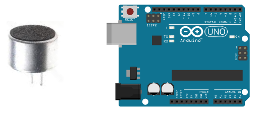
- A Condenser Microphone
- 6 Volts of power (either from 4 'AA' batteries or a DC power supply)
- 2KΩ-6KΩ resistor (depending on the microphone in use)
- 10Ω resistor
- 10KΩ potentiometer
- 2 10μF electrolytic capacitor
- 100μF electrolytic capacitor
- 0.1μF ceramic capacitor
- 47nF ceramic capacitor
- Arduino
- LED
Condenser microphones, resistors, capacitors, and the LM386 audio amplifer chip can be easily obtained from most electronic online retailers.
Before we show the complete schematic diagram of connecting a microphone to an arduino, we will first show the pinout of the LM386. This way, the connections that we make from the microphone to it will make more sense.
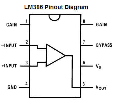
The pinout diagram is shown below:
Pin Terminals
Terminals 1 and 8 represent the gain control of the amplifier. These are the terminals
where you can adjust the gain by placing a resistor and capacitor or just capacitor between these
terminals. In this circuit, we will place a 10µF capacitor between these terminals for the highest voltage gain. You can adjust
this as necessary to adjust the gain, as needed.
Terminals 2 and 3 are the sound input signal terminals. These are the terminals where you place
the sound which you want to amplify. In our case for this circuit, the condenser microphone will be connected to these terminals.
Terminal 2 is the -input and Terminal 3 is the +input. In our circuit,
the positive microphone terminal will be placed on terminal 3 and terminal 2 will be connected to the negative microphone terminal, tied to ground.
Terminal 4 is GND (ground). This is where the negative voltage of the power source connects to.
Terminal 5 is the output of the amplifier. This is the terminal in which the amplified sound signal comes out.
Terminal 6 is the terminal which receives the positive DC voltage so that the op amp can receive
the power it needs to amplify signals.
Terminal 7 is the Bypass terminal. This pin is usually
left open or is wired to ground. However, for better stability, a capacitor is added in our circuit because this can prevent
oscillations in the amp chip.
Microphone Amplifier Circuit
Now that you what each of the pins of the LM386 represents, we can assemble the whole microphone amplifier circuit.
The schematic for the amplifier part of the circuit is shown below:
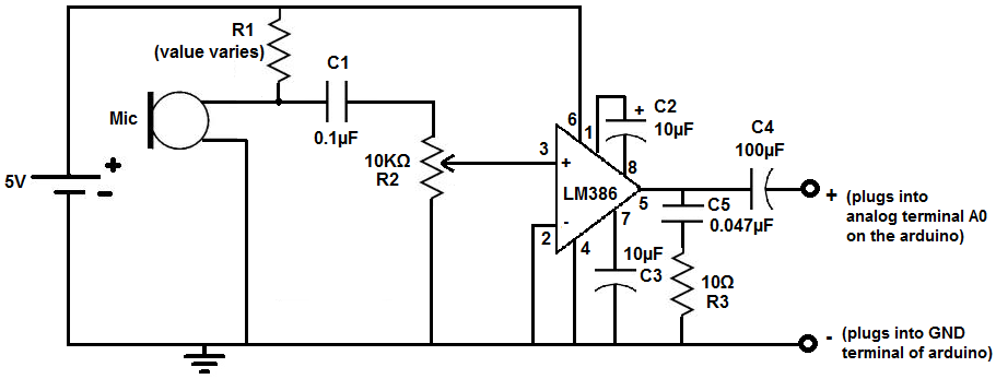
R1 is a resistor that connects the microphone to positive voltage so that the microphone is able to power on. Microphones cannot work without the necessary power needed. The value of the resistor is variable because it depends on the specific microphone that you have in use. Check the datasheet of the microphone you are using to find out the most suitable value for the necessary pull-up resistor.
C1 is a capacitor that blocks DC voltage on the input signal and allows AC to pass through. When we speak into a microphone, our voice or music is the AC signal. This is the only part of the signal that we want to pass through to output. The DC signal is only used to give power to the microphone; we do not want it to appear in output. This is why we use this capacitor. It blocks the DC but allows the AC to go into output.
R2 is a potentiometer that is used to control the sound volume.
C2 is a capacitor that sets the voltage gain of the LM386 amplifier. Therefore, the voltage out is 200 times the voltage in. This provides us with the maximum gain that the LM386 can provide.
C3 is a capacitor that improves the stability of the LM386 amplifier to prevent issues such as oscillations. Oscillation can distort sound signals, making them unclear or unintelligible.
C4 is a capacitor that removes any DC offset from the output of the LM386 amplifier.
C5 is a capacitor that acts as a current bank for output. This capacitor drains when sudden surges of current occur and refills with electrons when the demand for current is low.
The circuit starts with the condenser microphone. The microphone picks up sound signals and transforms them into electrical signals. These electrical signals
are then amplified by the LM386 IC. These signals are then output through pin 5 of the amplifier IC, which are then fed to the arduino board to be processed.
How to Connect the Microphone Circuit to an Arduino
The complete circuit is shown below:
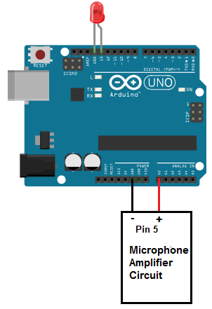
The output signal, again, comes from pin 5 of the LM386 IC. The positive terminal (+) goes into an analog terminal of the Arduino; we will connect it,
in our case,
to
A0 of the analog terminal. The negative terminal (-) connects to GND on the arduino. This allows us to process the output signal of the microphone. If we don't speak into the microphone,
it will pick up a faint signal and give us a very low reading. If we make loud noises such as shout, clap into the microphone, etc., we will get a loud reading.
We will program the software for the arduino to light up the LED attached to digital pin, D13, when a certain threshold of sound is reached. The LED will light up
for a half of second and then turn off each time this sound threshold is reached. The
LED will mimic each sound picked up by the microphone. This way, our circuit functions as a sound detector.
Code
The code to turn on an LED when sound is detected is shown below.
const int microphonePin= 0;
const int ledPin=13;
int sample;
const int threshold= 800;
void setup() {
pinMode (ledPin, OUTPUT);
Serial.begin(9600);
}
void loop(){
sample= analogRead(microphonePin);
if (sample > threshold)
{
digitalWrite (ledPin, HIGH);
delay (500);
digitalWrite (ledPin, LOW);
}
else{ digitalWrite(ledPin, LOW); }
}
This is the code needed to detect sound and turn on an LED each time a loud sound is detected by an arduino.
And this is how a microphone can be integrated with an arduino.
To see a demo of this circuit in real life, see the video below.
Related Resources
How to Drive a 7 Segment LED Display with an Arduno
How to Build a Dark-activated Light Circuit
How to Build a Hall Effect Sensor Circuit
How to Build a Touch Sensor Circuit
How to Build an Accelerometer Circuit
How to Build a Motion Detector Circuit
How to Build a Motion Detector Alarm Circuit