
How to Build a Night Light Circuit Using an Arduino

In this project, we will go over how to build a night light circuit using an arduino.
A night light circuit is a circuit which will turn on when nighttime comes, which is when it gets dark and the place could use some illumination.
It is a common household device that is sold by pretty much all the major retailers.
The device can sense when it gets dark and will switch on a light so that there can be some illumination.
The device we will build in this project will be automatic in nature. As soon as it gets dark, the LED attached to our arduino board will turn on right away, automatically.
For this project, the main component we will use is a photoresistor. When we place a photoresistor in series with a resistor, a voltage divider is formed. Voltage will be allocated to the 2 components based on the each one's respective resistance. More voltage will fall across the component with the greater resistance, according to ohm's law, V=IR. We will exploit this principle in this circuit to determine the light level that our circuit is exposed to and this will determine whether our LED turns on or off.
Components Needed for the Night Light Circuit
- Photoresistor
- 10KΩ Resistor
- Arduino
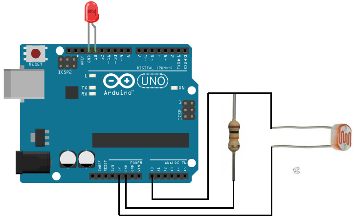
Night Light Circuit Schematic
The schematic for the night light circuit is shown below:
Code
The code to turn on an LED when the light level falls below a certain threshold is shown below.
const int ledPin=13;
const int sensorPin= 0;
int level;
const int threshold=150;
void setup() {
pinMode (ledPin, OUTPUT);
Serial.begin(9600);
}
void loop(){
level= analogRead(sensorPin);
if (level < threshold){
digitalWrite(ledPin, HIGH);
}
else{
digitalWrite(ledPin, LOW);
}
}
Here in this code, we first define the pin connections. Since the LED is connected to digital pin D13, we set the pin to 13. Since the sensorPin representing the photoresistor voltage divider is connected to analog pin A0, we set it equal to 0.
Next, we declare an integer named level. This will represent the light level of our circuit, meaning how much light the circuit is exposed to. We also declare a variable named threshold and set it equal to 150. We later have code that if the circuit's light level is less than the threshold, the LED will turn on.
The next line declares the ledPin as a digital output.
After this, the next block of code reads the value from the analog pin A0. If the light level is below the threshold, the LED will light up.
The biggest part of all of this is knowing how the voltage divider circuit works. The voltage divider is again formed between the photoresistor and the 10KΩ resistor. When exposed to near total darkness, the photoresistor has an extremely high resistance, in the order of several megohms. In fact, placing an ohmmeter across the leads of a photoresistor when covered in darkness or black clothing will yield resistance over 2MΩ. When the resistance is this high, most of the voltage from the 5V source feeding the voltage divider will fall across the photoresistor and very little voltage will fall across the 10KΩ resistor. Thus, the reading we will get from the analog pin A0 will be very low. Remember, the analogRead() function is a function that reads the analog value from an analog pin and the possible output values range from 0 to 1024. A low reading is on the low side of the values such as from 0 to 150. A high reading is from on the high side such as 800-1024. The analog pin A0 is reading the voltage across the 10KΩ resistor. When exposed to darkness, since the photoresistor has such great resistance, most voltage falls across it and very little across the resistor. Thus, if we get a very low sensor reading, we know that the circuit is exposed to darkness. We place our threshold value on the low end of the scale, at 150. If the level goes below 150, we know our circuit is exposed to darkness. In this case, the LED attached to digital pin D13 will turn on. This stimulates an automatic night light.
If, on the other hand, the circuit is exposed to normal room light, the photoresistor will significantly lower resistance. When measured at room light, the photoresistor measured about 30KΩ of resistance. At this resistance, much less voltage will fall across the photoresistor and more will fall across the resistor. Thus, the sensor reading will read a much higher value, in the 500s range. This will not trigger the LED to turn on because the level reading is higher than the low threshold value required for the LED to be lit. In this case, the circuit is exposed to a good deal of light and there is no need to have the LED lit, because it isn't a dark, night setting.
If a light is being shined on the photoresistor, the photoresistor's resistance will drop to 3KΩ or less. In this case, most of the 5V from the power source will fall across the 10KΩ resistor and not the photoresistor. The sensor reading will be very high, 800 or more. This will be way above the sensor threshold and the LED will not light.
And this is how an automatic night light circuit can be built with an arduino board.
To see this circuit in action as in real life, see the following video below:
Related Resources
How to Drive a 7 Segment LED Display with an Arduno
How to Build a Dark-activated Light Circuit
How to Build a Hall Effect Sensor Circuit
How to Build a Touch Sensor Circuit
How to Build an Accelerometer Circuit
How to Build a Motion Detector Circuit
How to Build a Motion Detector Alarm Circuit