How to Build a Traffic Light Circuit with an Arduino
In this project, we will go over how to build a traffic light circuit with an arduino microcontroller.
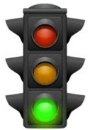
A traffic light circuit is a circuit which simulates how an actual traffic light works.
There is a green LED, which represents the green light. A yellow LED, which represents the yellow light. And a red LED, which represents the red light.
In our circuit, we will make it so that the green LED is on for 15 seconds, then the yellow LED turns on for 2 seconds, and then the red LED turns on for 15 seconds. And this repeats over and over again, as a traffic light would.
We will show all the hardware connections and the software needed to make this circuit work.
Once you know how the software operates, you can change the values to make the LEDs be on or off for any period of time.
For example, instead of being on for 15 seconds, you can easily change it to 10 seconds or 30 seconds. You could make the yellow
LED be on just for 1 second or 2.5 seconds.
Components
- Arduino Microcontroller
- Green LED
- Yellow LED
- Red LED
- 3 470Ω resistors
For this project, we need an arduino microcontroller such as arduino uno or duemilanove.
And we just need 3 LEDs, green, yellow, and red, along with 3 470Ω resistors which act as current-limiting
resistors to the LEDs, so that the LEDs don't burn out.
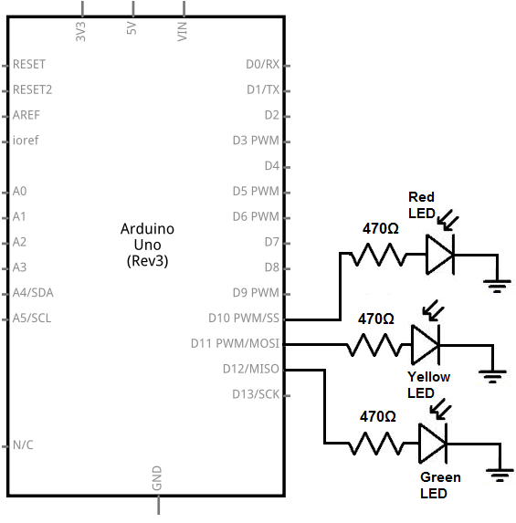
Arduino Traffic Light Circuit
The traffic light circuit we will build with an arduino is shown below.
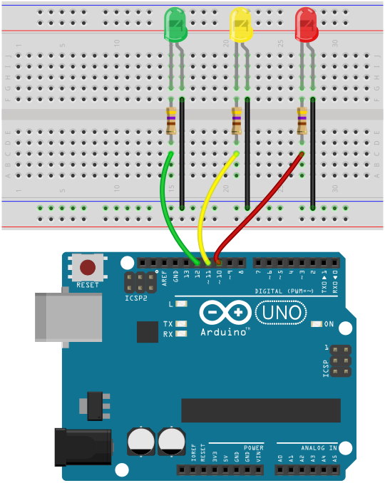
The breadboard schematic of the circuit above is shown below.
So for this circuit to work, we have our 3 LEDs. The anodes, the positive terminals of the LEDs, all connect to a digital pin on the arduino via a 470Ω current-limiting resistor.
The green LED connects to digital pin, D12, on the arduino.
The yellow LED connects to digital pin, D11, on the arduino.
The red LED connects to digital pin, D10, on the arduino.
All of these LEDs connect to these digital pins through a 470Ω resistor.
The cathodes, or negative terminals of the LEDs, connect to ground.
These completes all the hardware connections to the circuit.
How the circuit works is that we can control which LED is on because each LED is connected to a separate
digital pin on the arduino. If we make a digital pin HIGH, that LED is on, while the rest are written LOW and so are off.
With the software code, we can decide how long each LED is on for. This is explained in detail below.
Code
The code to simulate a traffic light circuit is shown below.
const int greenLED= 12;
const int yellowLED= 11;
const int redLED= 10;
void setup() {
pinMode (greenLED, OUTPUT);
pinMode (yellowLED, OUTPUT);
pinMode (redLED, OUTPUT);
}
void loop(){
digitalWrite (greenLED, HIGH);
digitalWrite (yellowLED, LOW);
digitalWrite (redLED, LOW);
delay(15000);
digitalWrite (greenLED, LOW);
digitalWrite (yellowLED, HIGH);
digitalWrite (redLED, LOW);
delay(2000);
digitalWrite (greenLED, LOW);
digitalWrite (yellowLED, LOW);
digitalWrite (redLED, HIGH);
delay(15000);
}
Here in this code, we first define the pin connections. Since the green LED is connected to digital pin 12, we set it equal to 12. Since the yellow LED is connected to digital pin 11, we set it equal to 11. Since the red LED is connected to digital pin 10, we set it equal to 10.
The next block of lines, the setup() function, declare all the LEDs as outputs. We are not reading any value from the LED. We are writing either a HIGH or LOW value to the LED. Therefore, the LEDs must be outputs, not inputs.
The next function, the loop() function, is the heart of our code. This block of code loops over and over and over again, repeatedly, without end.
In the first section, we write the greenLED HIGH while all the others are LOW. We call a delay of 15000 which is equal to 15 seconds. This causes the green LED to be on for 15 seconds, while all the other LEDs are off.
In the second section, we write the yellowLED HIGH while all the others are LOW. We call a delay of 2000, which is equal to 2 seconds. This causes the yellow LED to be on for 2 seconds, while the other LEDs are off.
In the third section, we write the redLED HIGH while all the others are LOW. We call a delay of 15000, which is equal to 15 seconds. This causes the red LED to be on for 15 seconds, while all the other LEDs are off.
Again, you can change the time the LEDs are on for by changing the value in the delay() function. Since the parameter in the delay() function is measured in milliseconds (ms), delay(1000) is 1 second. So if you want to have the LED on for 10 seconds, for example, the parameter would 1000 * 10= 10000. So the delay function would be delay(10000). If you want the LED on for 30 seconds, the parameter would be 1000 * 30= 30000. So the delay function would be delay(30000).
And this is how a traffic light can be simulated with an arduino microcontroller.
Related Resources
How to Drive a 7 Segment LED Display with an Arduno
How to Build a Dark-activated Light Circuit
How to Build a Hall Effect Sensor Circuit
How to Build a Touch Sensor Circuit
How to Build an Accelerometer Circuit
How to Build a Motion Detector Circuit
How to Build a Motion Detector Alarm Circuit