
Atmega328 Pinout
In this article, we will go over the pinout of the Atmega328 chip.
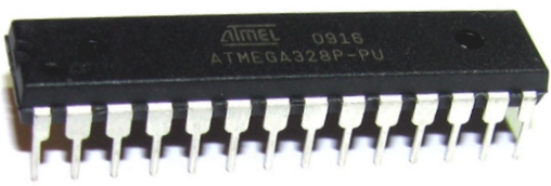
The Atmega328 is a very popular microcontroller chip produced by Atmel. It is an 8-bit microcontroller that has 32K of flash memory, 1K of EEPROM, and 2K of internal SRAM.
The Atmega328 is one of the microcontroller chips that are used with the popular Arduino Duemilanove boards. The Arduino Duemilanove board comes with either 1 of 2 microcontroller chips, the Atmega168 or the Atmega328. Of these 2, the Atmega328 is the upgraded, more advanced chip. Unlike the Atmega168 which has 16K of flash program memory and 512 bytes of internal SRAM, the Atmega328 has 32K of flash program memory and 2K of Internal SRAM.
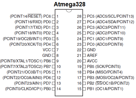
The Atmega328 has 28 pins.
It has 14 digital I/O pins, of which 6 can be used as PWM outputs and 6 analog input pins. These I/O pins account for 20 of the pins.
The pinout for the Atmega328 is shown below.
The table below gives a description for each of the pins, along with their function.
| Pin Number | Description | Function |
| 1 | PC6 | Reset |
| 2 | PD0 | Digital Pin (RX) |
| 3 | PD1 | Digital Pin (TX) |
| 4 | PD2 | Digital Pin |
| 5 | PD3 | Digital Pin (PWM) |
| 6 | PD4 | Digital Pin |
| 7 | Vcc | Positive Voltage (Power) |
| 8 | GND | Ground |
| 9 | XTAL 1 | Crystal Oscillator |
| 10 | XTAL 2 | Crystal Oscillator |
| 11 | PD5 | Digital Pin (PWM) |
| 12 | PD6 | Digital Pin (PWM) |
| 13 | PD7 | Digital Pin |
| 14 | PB0 | Digital Pin |
| 15 | PB1 | Digital Pin (PWM) |
| 16 | PB2 | Digital Pin (PWM) |
| 17 | PB3 | Digital Pin (PWM) |
| 18 | PB4 | Digital Pin |
| 19 | PB5 | Digital Pin |
| 20 | AVCC | Positive voltage for ADC (power) |
| 21 | AREF | Reference Voltage |
| 22 | GND | Ground |
| 23 | PC0 | Analog Input |
| 24 | PC1 | Analog Input |
| 25 | PC2 | Analog Input |
| 26 | PC3 | Analog Input |
| 27 | PC4 | Analog Input |
| 28 | PC5 | Analog Input |
As stated before, 20 of the pins function as I/O ports. This means they can function as an input to the circuit or as output. Whether they are input or output is set in the software. 14 of the pins are digital pins, of which 6 can function to give PWM output. 6 of the pins are for analog input/output.
2 of the pins are for the crystal oscillator. This is to provide a clock pulse for the Atmega chip. A clock pulse is needed for synchronization so that communication can occur in synchrony between the Atmega chip and a device that it is connected to.
The chip needs power so 2 of the pins, Vcc and GND, provide it power so that it can operate. The Atmega328 is a low-power chip, so it only needs between 1.8-5.5V of power to operate.
The Atmega328 chip has an analog-to-digital converter (ADC) inside of it. This must be or else the Atmega328 wouldn't be capable of interpreting analog signals. Because there is an ADC, the chip can interpret analog input, which is why the chip has 6 pins for analog input. The ADC has 3 pins set aside for it to function- AVCC, AREF, and GND. AVCC is the power supply, positive voltage, that for the ADC. The ADC needs its own power supply in order to work. GND is the power supply ground. AREF is the reference voltage that the ADC uses to convert an analog signal to its corresponding digital value. Analog voltages higher than the reference voltage will be assigned to a digital value of 1, while analog voltages below the reference voltage will be assigned the digital value of 0. Since the ADC for the Atmega328 is a 10-bit ADC, meaning it produces a 10-bit digital value, it converts an analog signal to its digital value, with the AREF value being a reference for which digital values are high or low. Thus, a portrait of an analog signal is shown by this digital value; thus, it is its digital correspondent value.
The last pin is the RESET pin. This allows a program to be rerun and start over.
And this sums up the pinout of an Atmega328 chip.
Related Resources
How to Use the LM741 Op Amp as a Comparator
How to Build an LM339 Quad Voltage Comparator Circuit
How to Build a Dark-activated Switch
How to Build a Hall Effect Sensor Circuit
How to Build a Touch Sensor Circuit
How to Build an Accelerometer Circuit
How to Build a Motion Detector Circuit
How to Build a Motion Detector Alarm Circuit