How to Build a Difference Amplifier Circuit
In this circuit, we will show how to build a difference amplifier using an LM741 operational amplifier chip.
A difference amplifier is an amplifier that outputs the difference of the voltages input into the op amp.
So if we feed voltages into the inverting and noninverting terminals of the op amp, the output of the op amp will be the voltage at the noninverting terminal minus the voltage at the inverting terminal. Thus, it computes the difference of the 2 voltages.
It can be seen as a subtraction mathematical operator.
Components
- LM741 op amp chip
- 4 10KΩ resistors
The LM741 is an operational amplifier IC that we use to build this difference amplifier.
The LM741 is an 8-pin chip.
In order to know how to build this circuit, you must know the pinout of an LM741, in order to connect the pins properly.
Below is the pinout of the LM741 op amp chip.
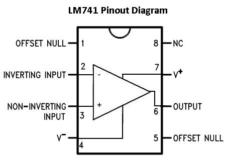
Pin 1: Offset Null- This is the pin where we add voltage to if we want to eliminate the offset voltage.
This is if we want to completely balance the input
voltages. More on this at offset terminals
Pin 2: Inverting Input- This is where the positive part of the input signal that we want to
amplify goes if we want our amplified signal inverted. If we don't want it inverted, we place the positve
part of the signal into the Non-inverting terminal and place the negative or ground part of our signal
here.
Pin 3: Non-inverting Input- This is where the positive part of the input signal that we want
amplified goes if we want our signal non-inverted.
Pin 4: V-- The LM741 Op amp is a dual power supply op amp, meaning it must be supplied positive
DC voltage and negative DC voltage. Pin 4 is where the op amp gets supplied with negative DC voltage.
Pin 5: Offset Null- This is the pin where we add voltage to if we want to eliminate the offset voltage.
This is if we want to completely balance the input
voltages. More on this at offset terminals
Pin 6: Output- This is the terminal where the output, the amplified signal, comes out of. Whatever
output the amplifier will drive gets connected to this terminal.
Pin 7: V+- This is the terminal which receives the positive DC voltage.
Pin 8: NC- This pin stands for Not Connected. It is not used for anything and should be left open.
Difference Amplifier Circuit
The difference amplifier circuit we will build with an LM741 op amp chip is shown below.
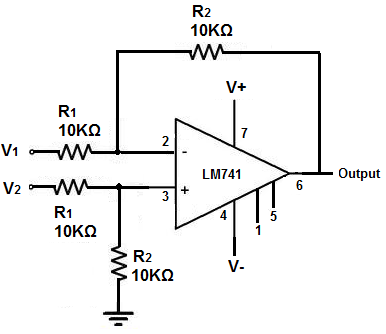
First you determine the voltage at the noninverting input by using the voltage divider relation, with the assumption that no current enters the inputs.
V+ = R2/(R1 + R2) V2
Next you apply Kirchhoff's current junction law to the inverting input (I1= I2): (V1) - V-)/R1= (V- - VOUT)/R2
Now substituting the V+ term in for V- in the last equation, we get:
VOUT= R2/R1= (V2 - V1)
Since R1= R2, then VOUT= V2 - V1
So whatever we feed into the noninverting and inverting terminals, the output voltage will be the voltage at the noninverting terminal minus the inverting terminal.
So if we feed 5V into V1 and 3V into V2, then the output voltage will be 2V (5V - 3V= 2V).
And this is how a difference amplifier can be built with an LM741.
Related Resources
How to Build a Voltage Gain Op Amp Circuit
How to Build a Non-inverting Op Amp Circuit
How to Build an Inverting Op Amp Circuit
How to Build an Integrator Op Amp Circuit
How to Build a Differentiator Op Amp Circuit
How to Build a Summing Amplifier Circuit