
How to Build a Differentiator Op Amp Circuit
In this circuit, we will show how to build a differentiator op amp circuit using an LM741 operational amplifier chip.
A differentiator circuit is a circuit that performs the mathematical operation of differentiation.
Differentiation is the mathematical operation that calculates the instantaneous rate of change of the function.
Looking at differentiation from a graphical point of view, it visually shows the slope of a function at any given point of a function. It's a little hard to understand without seeing it visiually on a graph, but just know that it represents the slope of a function.
So, for example, let's say there is a function of a triangle wave. The output differentiated signal will be a square wave signal. This is because the derivative of a triangle wave is a square wave. If you took a triangle wave and computed the instantaneous rate of change at every given point of it, the a square wave would represent the rates of change at each point on the triangle wave.
Differentiation is a calculus function that is the opposite of integration.
So if you perform a differentiation operation and then you perform an integration operation, you get the original function, because integration is the opposite or undoing of differentiation.
An integrator circuit would be the exact opposite. If you fed a square wave signal into it, you would get a triangle wave output.
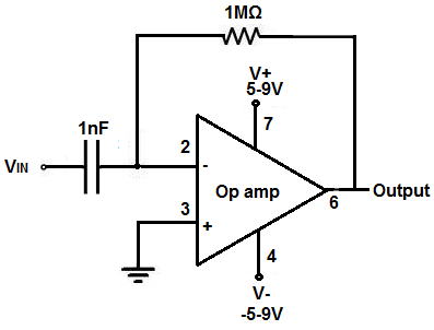
So if we feed a voltage signal into the inverting terminal of the op amp with a capacitor at the input and a resistor going from the input to the output with the noninverting terminal of the op amp grounded, it will differentiate that voltage signal. Out of the output of the op amp will be the differentiated voltage signal.
So, again, if we feed a saw tooth or triangle wave signal into the input of the op amp, from the output
will be a square waveform. This is because
when a triangle waveform is differentiated, the output is a square waveform signal.
Components
- LM741 op amp chip
- 1MΩ resistor
- 1nF ceramic capacitor
The LM741 is an operational amplifier IC that we use to build this differentiator op amp circuit.
The LM741 is an 8-pin chip.
In order to know how to build this circuit, you must know the pinout of an LM741, in order to connect the pins properly.
Below is the pinout of the LM741 op amp chip.
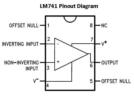
Pin 1: Offset Null- This is the pin where we add voltage to if we want to eliminate the offset voltage.
This is if we want to completely balance the input
voltages. More on this at offset terminals
Pin 2: Inverting Input- This is where the positive part of the input signal that we want to
amplify goes if we want our amplified signal inverted. If we don't want it inverted, we place the positve
part of the signal into the Non-inverting terminal and place the negative or ground part of our signal
here.
Pin 3: Non-inverting Input- This is where the positive part of the input signal that we want
amplified goes if we want our signal non-inverted.
Pin 4: V-- The LM741 Op amp is a dual power supply op amp, meaning it must be supplied positive
DC voltage and negative DC voltage. Pin 4 is where the op amp gets supplied with negative DC voltage.
Pin 5: Offset Null- This is the pin where we add voltage to if we want to eliminate the offset voltage.
This is if we want to completely balance the input
voltages. More on this at offset terminals
Pin 6: Output- This is the terminal where the output, the amplified signal, comes out of. Whatever
output the amplifier will drive gets connected to this terminal.
Pin 7: V+- This is the terminal which receives the positive DC voltage.
Pin 8: NC- This pin stands for Not Connected. It is not used for anything and should be left open.
Differentiator Op Amp Circuit
The differentiator op amp circuit we will build with an LM741 op amp chip is shown below.
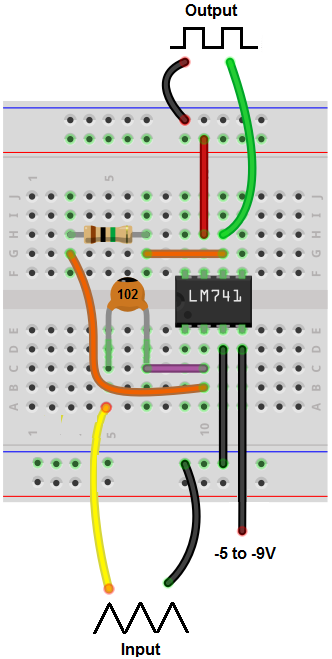
Below is the breadboard circuit of the above circuit.
So, when there is a capacitor at the input to the inverting terminal and a resistor with one side connected to the inverting terminal and the other side to the output, we have a differentiator circuit.
So the first thing to consider about this circuit is power requirements.
Since we're dealing with AC signals, such as square, triangle, and sine waves, the LM741 must be supplied with a dual power supply. What this means is a positive voltage must be fed into the op amp along with a negative voltage. The reason this is done is so that positive and negative DC rails can be established for the op amp. Now the AC signal, whether a square wave or a triangle wave or a sine wave, can swing from those 2 rails. Say, for instance, we feed +5V and -5V into our circuit, the AC signal can now then swing from up to +5V to -5V. If we feed +10V and -10V into the op amp, the AC signal has even more room now to swing; it can swing from +10V to -10V. If you see clipping on the output signal, this means the rails aren't high enough or the input signal is too high. You either have to increase the rails or decrease the amplitude of the input signal to eliminate the clipping.
In this circuit, we use about +9V and -9V for the DC rails for the op amp. This is sufficient for basic purposes.
+9V is fed into V+, pin 7.
-9V is fed into V-, pin 4.
This establishes power for the op amp circuit.
Pins 1, 5, and 8 are not used in this circuit, so these pins are simply left unconnected.
The next thing to consider is the value of the RC network across the inverting terminal and the output of the op amp.
In this circuit, we're using a 1MΩ resistor and a 1nF capacitor. Doing the math, this circuit deals with frequencies that are very low, in the hundreds of hertz. So this circuit will differentiate signals near the 100s of hertz range. It doesn't work for all frequencies. It only works for frequencies that are compatible with the values of the RC network. The circuit won't work for frequencies well outside this range. So the input signal for this circuit has to be lower than about 1KHz; otherwise, the circuit will not produce proper output.
So be aware that the frequency of the input signal must be compatible with the values being used for the resistor and capacitor.
For this differentiator circuit, if a triangle wave is input into the circuit, the output will be a square wave.
So if you connect an oscilloscope to the output of this circuit, with a triangle wave as the input, you should get a square wave at the output.
And this is how a differentiator op amp circuit can be built with an LM741.
To see how this circuit operates in real life, see the video below.
Related Resources
How to Build a Voltage Gain Op Amp Circuit
How to Build a Non-inverting Op Amp Circuit
How to Build an Inverting Op Amp Circuit
How to Build a Difference Amplifier Circuit
How to Build an Integrator Op Amp Circuit
How to Build a Summing Amplifier Circuit