
How to Build an Summing Op Amp Circuit
In this circuit, we will show how to build an summing op amp circuit using an LM358 dual operational amplifier chip.
A summing circuit is a circuit that performs the mathematical operation of addition. It adds up all the voltages that are input to the op amp.
In this circuit, we use 3 inputs so it adds up all 3 inputs into the op amp. The sum, which is the result of addition operation, is given at the output of the op amp.
So, for example, if we have input voltages of 1V, 3V, and 5V, this will produce a voltage of 9V at the output.
A summing amplifier is used for many different purposes where we need signals either added or blended in. One place where summing amplifier
circuits are used is in audio mixers. An audio mixer really is a device that blends or mixes in different audio signals. It literally is an adder or summing
amplifier. To insert another audio signal, we simply add it in. The signal at the output is the sum of the individual audio signals. So summing
amplifier circuits can be used for any circuits where we need multiple signals blended in or mixed together at the output.
Components
- LM358 dual op amp chip
- 2 1KΩ resistors
- 4 10KΩ resistors
The LM358 is a dual operational amplifier IC that we use to build this summing op amp circuit.
The LM358 is an 8-pin chip.
The datasheet for the LM358 chip can be found at the following link: LM358 Dual Op Amp Datasheet
It has 2 operational amplifiers that are completely independent of each other.
In order to know how to build this circuit, you must know the pinout of an LM358, in order to connect the pins properly.
Below is the pinout of the LM358 op amp chip.
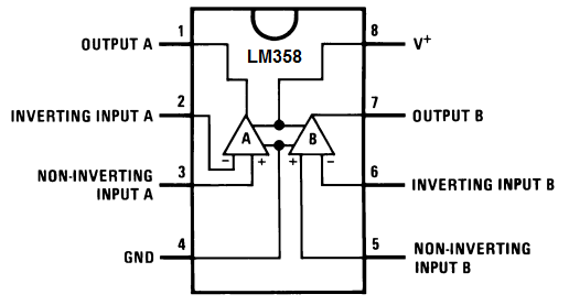
Pin 1 is the output of the first op ap. Since we are using 2 op amps and connecting them together, this output will feed into the input of the second op amp.
Pin 2 is the inverting terminal of the first op amp. This is the terminal where we will connect our 3 input voltage signals.
Pin 3 is the noninverting terminal. We simply connect this terminal to ground.
Pin 4 is the GND terminal. We either connect this pin to ground or to negative voltage.
Pin 5 is the noninverting terminal of the second op amp. Just like the first op amp, this terminal is grounded.
Pin 6 is the inverting terminal of the second op amp. The output from the first op amp gets fed into this terminal.
Pin 7 is the output terminal of the second op amp. There is where we get our true output from. This output will have a voltage that is the sum of the 3 individual voltages that we input into the inverting terminal of the first op amp.
Pin 8 is the V+ pin. This is the terminal where we connect positive voltage to.
Summing Op Amp Circuit
The summing op amp circuit we will build with an LM58 dual op amp chip is shown below.
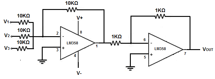
For this circuit, we use both op amps. We need both op amps in order to build this adder.
For this circuit, we create 3 inputs. All the inputs are connected to the inverting terminal of the first op amp.
These inputs determine the voltage that will appear at the output.
How the Circuit Works
So we have 3 inputs in the circuit.
These 3 inputs determine the voltage at the output. The addition of these 3 voltage inputs is the voltage output.
So we simply insert different voltage lines to the inputs. And the output will be the sum of them.
The second op amp simply acts as a buffer, so that when the circuit is powering a load, there is not a drop in the output voltage.
And this is how an summing op amp circuit can be built with an LM358.
Related Resources
How to Build a Voltage Gain Op Amp Circuit
How to Build a Non-inverting Op Amp Circuit
How to Build an Inverting Op Amp Circuit
How to Build a Difference Amplifier Circuit
How to Build an Integrator Op Amp Circuit
How to Build a Differentiator Op Amp Circuit