How to Build a Flex Sensor Circuit with a Voltage Comparator
In this project, we will show how to build a flex sensor circuit using a voltage comparator IC.
This allows us to bypass having to use a microcontroller in order to read and interpret the output value from the flex sensor, which is really the only other way of being able to read and interpret values from the flex sensor.
Thus, with a simple, cheap voltage comparator IC, which you can get for a few cents, well under $1.00, you can interpret the value from a flex sensor and alow the circuit to take action when the flex sensor is flexed.
A flex sensor is a device that has very versatile compatibilities. When the sensor is flexed, its resistance increases significantly. Using a voltage divider circuit, comprising of the flex sensor and a carefully chosen fixed resistor, we can know when the sensor is being flexed and when it is not. We will go into extreme detail on how this works.
Flex sensors are put into all types of objects, one of the most prominent being stuffed animal toys or dolls, where when you squeeze the arm or other part of its body, it does something such as say a phrase. Flex sensors circuits have also been used in game controllers such as the Nintendo Glove. Thus, they have widespread application and can fit in into many types of circuits.
In the circuit we will build, when the flex sensor is flexed, we will make an LED light up. As soon as we
allow the sensor to snap back into its unflexed state, the LED will shut off. So the load of the circuit, which is an LED,
will turn on only when the flex sensor is flexed.
Components Needed
- 2.2" Flex Sensor
- LM324 Voltage Comparator IC
- 330Ω Resistor
- LED
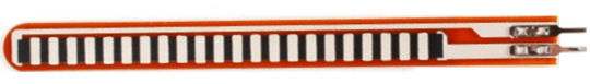
The flex sensor we will use in this circuit is the 2.2" flex sensor patented and produced by Spectra Symbol.
The flex sensor we will use has a flat resistance of 25KΩ and a bend resistance of 45KΩ to 125KΩ, depending on how much it is flexed. The flat resistance is the resistance of the flex sensor when it is unflexed. And the bend resistance is the resistance of the flex sensor when it is bent. The larger the angle that the sensor is bent, the greater the resistance.
If you have a multimeter or an ohmmeter, do a test to check the resistance values you obtain when the sensor is unflexed and flexed. Note these readings. If you do not have a way of checking the resistance yourself, then your next bet is just to follow the datasheet.
The datasheet for the 2.2" flex sensor by Spectra Symbol is at the following link: Spectra Symbol 2.2" Flex Sensor Datasheet.
The voltage comparator IC we will use is the LM324, since it is a recommended comparator IC to use with the
flex sensor on the sensor's datasheet. This is a quad op amp comparator; however, in this circuit, we will just be using
one op amp.
Flex Sensor Circuit Schematic
The flex sensor circuit we will build is shown below.
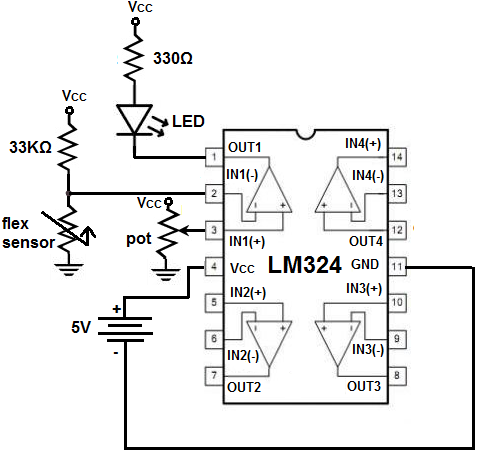
For our circuit, we create a voltage divider between the flex sensor and a fixed resistor. Since the flex sensor has a flat resistance of 25KΩ and a bend resistance of 45KΩ to 125KΩ, we want a fixed resistor that has a value between these 2 resistance values (the flat and the bend). So for this sensor, we will use a 33KΩ resistor. When the sensor is unflexed, its resistance will be below 33KΩ. When it is flexed, it will be above 33KΩ. We'll explain how this works specifically with our voltage comparator IC.
Our voltage comparator IC, the LM324, has 4 op amps. But we will just be using one of them. Each op amp has 2 inputs and 1 output. The 2 inputs are an inverting terminal and a noninverting terminal. How the op amp works is when the voltage at the inverting terminal is greater than at the noninverting terminal, then the output is drawn high to Vcc and the load is powered. When the voltage at the inverting terminal is less than the noninverting terminal, then the output is drawn low to GND and the load cannot be powered. This is how an op amp works.
How we configure our circuit is we connect our voltage divider circuit, the flex sensor and the fixed resistor, to the inverting terminal of the op amp. To the noninverting terminal, we connect the wiper terminal of a potentiometer. One end of the potentiometer we connect to Vcc and the other end we connect to ground. Vcc will be about 5V. Adjust the potentiometer so that it is adjusted about midway so that it has a voltage of about Vcc/2, or 2.5V.
With this setup, our circuit will work. When the flex sensor is not flexed, its resistance is 25KΩ, below the 33KΩ fixed resistor. Thus, most of the voltage from the VCC power supply will fall across the fixed resistor, well more than half, and very little voltage falls across the flex sensor. Thus, the voltage at the inverting terminal will be lower than the 2.5V at the noninverting terminal. Since the voltage at the inverting terminal is lower than at the noninverting terminal, the output will be drawn down to GND and the load, which is an LED, will be off.
When the flex sensor is flexed, however, its resistance increases significantly, well above the 33KΩ fixed resistor. Thus, most of the voltage from VCC will fall across it. Thus, in this case, the voltage at the inverting terminal will be greater than at the noninverting terminal, and the output will be drawn up to VCC, so the LED will be powered on.
And this is how the circuit operates.
Related Resources
How to Use the LM741 Op Amp as a Comparator
How to Build an LM339 Quad Voltage Comparator Circuit
How to Build a Dark-activated Switch
How to Build a Hall Effect Sensor Circuit
How to Build a Touch Sensor Circuit
How to Build an Accelerometer Circuit
How to Build a Motion Detector Circuit
How to Build a Motion Detector Alarm Circuit