
How to Build an LC Resonant Circuit

In this circuit, we show how to build an LC resonant circuit.
An LC resonant circuit is a circuit that is composed of a single inductor and capacitor that can do many powerful and useful things.
An LC resonant circuit, as the name implies, achieves resonance. You can think of resonance as just the right frequency achieved so that the output signal reaches a perfect state of oscillations. These oscillations manifest themselves as sine waves. So when resonance is achieved, sine wave signals will be output.
So an LC resonant circuit is able to output sine waves. Thus, LC resonant circuits are used many times to create sine wave signal generators.
In this circuit, actually, we will build the simplest LC resonant circuit that can be built. We will input a square wave signal into the LC resonant circuit and at the output we will get a sine wave signal.
This is actually a powerful illustration of resonance and how it can be used to changed signals, in this case square wave signals into sine wave signals.
We will show how to build this below.
Components Needed
- 470µH inductor
- 1µF ceramic capacitor
Inductors and capacitors can be obtained very cheaply at a number of online retailers. It can be obtained at Tayda Electronics at the following link: Tayda Electronics.
All we need in this circuit is a single inductor and a single capacitor. Using just these 2 components, we can achieve resonance in our circuit.
LC Resonant Circuit
The schematic diagram of the LC resonant circuit we will build is shown below.
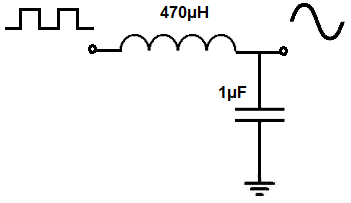
The breaboard circuit of the circuit above is shown below.
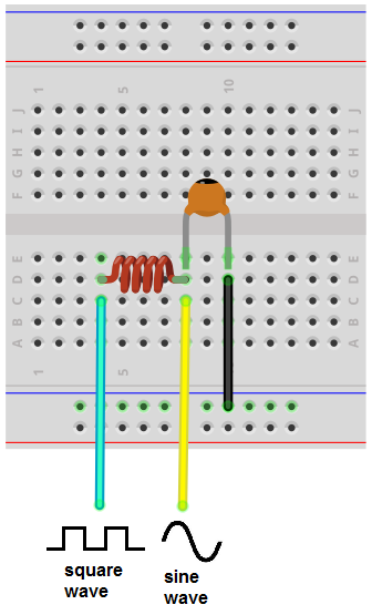
So this circuit, again, as it appears above, is very basic.
It's an LC resonant circuit- it's composed of a single inductor and capacitor.
So into this circuit we feed a square wave signal and at the output we get a sine wave signal.
It looks very basic on the outside but it requires a decent amount of math to get it to work.
So the math comes down to how to choose the values of the LC network, the inductor and the capacitor. How do we choose the values so that resonance can be achieved?
And the values are chosen based on the frequency of the signal entering the LC network.
In this case, since we are feeding a square wave signal into the LC network, we must consider the frequency of the square wave signal. Based on this frequency, we decide the values of the inductor and capacitor, so that resonance can be achieved.
How resonance works and how it's acheived is that the input signal (the square wave) must match the resonant frequency created by the LC network. When the frequency of the input signal matches the frequency created by the LC network, resonance is achieved; this resonance shows itself as a sine wave.
So let's say the frequency of the input square wave signal is 7KHz. How do we calculate the LC network to have a resonant frequency of 7KHz to match this frequency, so that we can get resonance?
And there is a formula to achieve this.
This formula is, frequency=
1/2π√
To have a calculator calculate the inductor and capacitor values that you need based on the resonant frequency you desire, see our LC Resonance Calculator. It will automatically compute what inductor and capacitor values you need for a given resonant frequency.
So that's how this circuit operates.
With the input signal (square wave) being about 7KHz and the LC frequency being around 7KHz, resonance is achieved and we get a sine wave signal at the output. The square wave is converted to a sine wave.
So now you can see the power and importance and an LC resonant circuit and the useful effect it achieves in this circuit
of converting a square wave signal into a sine wave signal.
To see how this circuit works in real life, see the following video below.
Related Resources
How to Use the LM741 Op Amp as a Comparator
How to Build an LM339 Quad Voltage Comparator Circuit
How to Build a Dark-activated Switch
How to Build a Hall Effect Sensor Circuit
How to Build a Touch Sensor Circuit
How to Build an Accelerometer Circuit
How to Build a Motion Detector Circuit
How to Build a Motion Detector Alarm Circuit