
How to Connect an MP3002 ADC Chip to a Raspberry Pi
In this article, we will show how to connect a MP3002 analog-to-digital converter (ADC) chip to a Raspberry Pi so that we can process analog input with the Raspberry Pi.
Let's first go over why we need to use a MCP analog to digital converter. And the reason is because a Raspberry Pi is not equipped with an internal ADC chip. Therefore, by itself, it cannot process analog input.
Analog input is very important to process because of the amount of signals in the world which are analog in nature. These include temperature, resistance, voltage, sound, etc. There are so many possibilities.
However, without an ADC, the Raspberry Pi is hopeless to process these analog signals. The Raspberry Pi, by itself, can only handle digital data. It cannot process analog data.
Therefore, this is where an ADC such as the popular MCP3002 comes in. With this ADC chip, we can now input and process analog signals with the Raspberry Pi. So now we can use microphones, sensors including photoresistors, flex sensors, force-sensing resistors, etc, with the Raspberry Pi. We input the analog signal into the MCP3002 and it converts it into its equivalent digital value. The MCP3002 is a 10-bit ADC chip, so it converts the analog signal into a 10-bit digital value.
The MCP3002 is perfect for integrating with a Raspberry Pi because it allows us to be able to build circuits based on analog input.
Now that we know the use of the MCP3002, we will go over in detail its pinout, so that you can learn how to connect it to a Raspberry Pi.
The MCP3002 is an 8-pin chip. Its pinout is shown below.
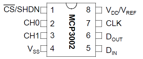
The Chip Select (CS) pin, pin 1, allows us to choose which channel of the Raspberry Pi the ADC chip will communicate with. The Raspberry Pi can communicate with up to 2 devices on a shared SPI Bus (shared clock and data connections) on its CS0 and CS1 pins. CS0 stands for chip select 0 and it represents one channel the Raspberry Pi offers. CS1 stands for Chip Select 1 and it represents another channel it offers. The Chip Select (CS) pin of the MCP3002 ADC decides which one of the 2 channels of the Raspberry Pi we will communicate with, CS0 or CS1. In our circuit, we will connect to the Raspberry Pi's CS0 pin. Therefore, we connect pin 1 of the MCP3002, the Chip Select pin, to CS0 of the Raspberry Pi. This makes us communicate with Raspberry Pi's Channel 0.
The 2 analog input pins of the MCP3002 are pins 2 and 3, CHO and CH1. These are the 2 pins where we place the analog signal that we want converted into a digital signal. Usually, we will only use 1 of the 2 of these pins. In our circuit we will build, since we have only one analog input, we will just use CH0 and ground CH1. CH0 stands for Channel 0 Analog Input. CH1 stands for Channel 1 Analog Input.
VSS is where we connect our power ground to. It establishes ground for the power we must feed to the chip.
The 2 data pins on the MCP3002 are DIN and DOUT, pins 5 and 6. On the Raspberry Pi the 2 data pins are MOSI and MISO. Therefore, we connect the MOSI to DIN and MISO to DOUT.
The CLK pin of the MCP3002, pin 7, is the pin that requires a clock pulse. This is the timing signal used to coordinate the data between the Raspberry Pi and the MCP3002. In order to convert analog signals to digital signals, the Raspberry Pi and the MPC3002 ADC chip need a way to be synchronized and know how to act together in synchrony. This is done through a clock signal. This way, the MCP3002 and Raspberry Pi act together to precisely change the analog signal to its corresponding digital value. Therefore, the CLK pin of the MCP3002 connects to the CLK pin of the Raspberry Pi.
VDD, sometimes referred to as VREF, pin 8, is where we place our positive voltage to in the MCP3002 chip to give it the power it needs to operate. The MCP3002 chip works off of a single supply operation of 2.7V to 5.5V. (Single supply means it only needs one power supply source.) In our circuit, for all basic purposes, we will connect VDD to the 3.3V pin of the Raspberry Pi. 3.3V of power will power the MCP3002 perfectly well for our purposes.
These are all the pins of the MCP3002.
The table below gives a summary to the connections of the MCP3002 pins to the Raspberry Pi.
| MCP3002 pin connects to Raspberry Pi Pin... | ||
| MCP3002 | Raspberry Pi | |
| CS | Pin 1 | CS0 or CS1 |
| CH0 | Pin 2 | Analog Input (not Raspberry Pi) |
| CH1 | Pin 3 | Analog Input (not Raspberry Pi)* |
| VSS | Pin 4 | GND |
| DIN | Pin 5 | MOSI |
| DOUT | Pin 6 | MISO |
| CLK | Pin 7 | SCLK |
| VDD | Pin 8 | 3V3 |
*If only using one analog input, this may be left either unconnected or grounded.
Now that we know what all the pins are and how they connect to the Raspberry Pi, we're going to show an example circuit so that it can be seen clearly how an actual circuit which takes in an analog input into a Raspberry Pi works in real life.
We're going to take the most basic example of all. We're going to take a potentiometer as an analog input into
a Raspberry Pi and process it. A potentiometer works as a perfect analog example because just by simply adjusting the knob,
we produce a plethora of analog values that the Raspberry Pi will now be able to read, simply because of the MCP3002 ADC chip.
Raspberry Pi Potentiometer Circuit
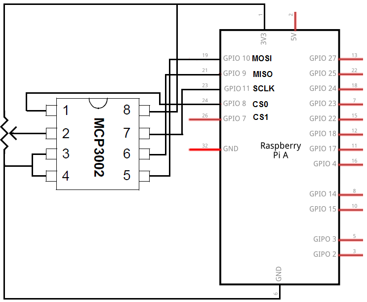
The basic circuit we will build that can read and interpret the values of a potentiometer, which is an analog input, is shown below.
The MCP3002 chip is integral to the process of interpreting the analog voltage signals from the potentiometer because it allows us to convert the analog signals to digital signals, which
are the only type of signals that the Raspberry Pi can read.
The breadboard schematic of the circuit above is shown below.
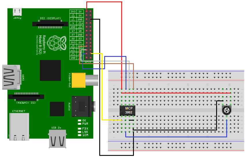
Now that you know how to connect the MCP3002 to the Raspberry pi, the only other connections are of the potentiometer.
The potentiometer is a 3-terminal device. It has 2 end terminals and 1 wiper terminal, which represents the adjustable terminal that allows for a change of resistance. This wiper
terminal gets connected into the CHO, analog input channel 0 of the MCP3002. These are the analog signals that gets converted into digital signals by the MCP3002. The Raspberry then takes the
digital signals and feeds them into the Raspberry Pi, which can interpret them.
Code
Besides physical connection, we now need the code which can read and display the values of the potentiometer at any given point during its adjustment.
The botbook_mcp3002 library which you need to import into your code can be obtained at the following link: botbook_mcp3002.You just have to copy the contents of the page this redirects you to and save it as a .py file (a python file).
The code is shown below.
import time
import botbook_mcp3002 as mcp #
def readPotentiometer():
global potentiometer
potentiometer = mcp.readAnalog() #
def main():
while True: #
readPotentiometer() #
print("The current potentiometer value is %i " % potentiometer) #
time.sleep( 0.5) # s
if __name__ = = "__main__":
main()
The botbook.com library for MCP3002 saves a lot of coding and makes it easy to read analog input.
The library must be in the same directly as this above coding file. You must also install the Spidev library, which is imported by botbook_mcp3002.
In the code, we created a readPotentiometer() function which reads the analog value from the wiper terminal of the potentiometer. We then call the function and print the potentiometer value. It's very basic code, with this library.
And this is how a MCP3002 can allow a Raspberry Pi to read and interpret analog input.
Related Resources
How to Use the LM741 Op Amp as a Comparator
How to Build an LM339 Quad Voltage Comparator Circuit
How to Build a Dark-activated Switch
How to Build a Hall Effect Sensor Circuit
How to Build a Touch Sensor Circuit
How to Build an Accelerometer Circuit
How to Build a Motion Detector Circuit
How to Build a Motion Detector Alarm Circuit