
MQ-2 Smoke Sensor Circuit Built with an Arduino

In this project, we will go over how to build a smoke sensor circuit with an arduino board.
The smoke sensor we will use is the MQ-2. This is a sensor that is not only sensitive to smoke, but also to flammable gas.
The MQ-2 smoke sensor reports smoke by the voltage level that it outputs. The more smoke there is, the greater the voltage that it outputs. Conversely, the less smoke that it is exposed to, the less voltage it outputs.
The MQ-2 also has a built-in potentiometer to adjust the sensitivity to smoke. By adjusting the potentiometer, you can change how sensitive it is to smoke, so it's a form of calibrating it to adjust how much voltage it will put out in relation to the smoke it is exposed to.
We will wire the MQ-2 to an arduino so that the arduino can read the amount of voltage output by the sensor
and sound a buzzer if the sensor outputs a voltage above a certain threshold. This way, we will know that the sensor is
detecting smoke and we will sound a buzzer alerting a person such as a homeowner to this fact.
Components Needed for Arduino Smoke Sensor Circuit
- MQ-2 Smoke Sensor
- Arduino board
- Buzzer
The MQ-2 can be obtained very cheaply, just a few bucks. A good place to look for it is on ebay, which always has auctions on them for the $2-$3 range.
Important, it is recommended that you do not obtain the standalone sensor but the whole MQ-2 board. This is because if you buy the standalone sensor, you will have to finish building the whole schematic before you can connect it to the arduino. So that less work is required for integrating this with the arduino, it is recommended that you buy the complete MQ-2 sensor circuit. This you can see below.
If you buy the complete board, there are 3 leads which need to be connected.
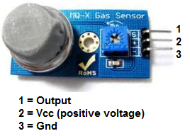
The 3 leads are Output, Vcc, and GND.
It's very basic.
The gas sensor needs about 5 volts of power in order to operate. This is done by connecting 5 volts to Vcc and GND.
The Output pin gives out the voltage reading, which is proportional to the amount of smoke that the sensor is exposed to. Again, a high voltage output means the sensor is exposed
to a lot of smoke. A low or 0 voltage output means the sensor is exposed to either little or no smoke.
Arduino MQ-2 Smoke Sensor Circuit Schematic
The circuit we will build is shown below.
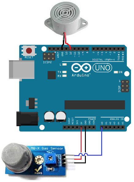
So to power the smoke sensor, we connect pin 2 of the smoke sensor to the 5V terminal of the arduino and terminal 3 to the GND terminal of the arduino. This gives the smoke sensor the 5 volts it needs to be powered.
The output of the sensor goes into analog pin A0 of the arduino. Through this connection, the arduino can read the analog voltage output from the sensor. The arduino board has a built-in analog-to-digital converter, so it is able to read analog values without any external ADC chip.
Depending on the value that the arduino reads determines the action that will occur with the circuit. We will make it in our code that if the sensor outputs a voltage above a certain threshold, the buzzer will go off, alerting a user that smoke has been detected.
These are all the physical connections in order for our circuit to work.
Code for the Arduino MQ-2 Smoke Sensor Circuit
Being that we've just gone over the circuit schematic for the smoke sensor circuit, all we need know is the code necessary to upload to the arduino for this smoke alarm cicrcuit to work.
The code that we need to upload is shown below.
const int sensorPin= 0;
const int buzzerPin= 13;
int smoke_level;
void setup() {
Serial.begin(115200);
pinMode(sensorPin, INPUT);
pinMode(buzzerPin, OUTPUT);
}
void loop() {
smoke_level= analogRead(sensorPin);
Serial.println(smoke_level);
if(smoke_level > 200){
digitalWrite(buzzerPin, HIGH);
}
else{
digitalWrite(buzzerPin, LOW);
}
}
The first block of code declares and initializes 3 variables. The sensorPin represents the smoke sensor. It is initialized to 0, because it will be connected to analog pin A0 of the arduino board. The next variable, buzzerPin, represents the pin that the anode of the buzzer will be connected to; it is initialized to 12 because it will be connected to digital pin D12 of the arduino board. And the variable, smoke_level, represents the amount of smoke that the smoke sensor picks up.
The next block of code defines the baud rate and the input and output of the circuit. The sensorPin, which is the smoke sensor pin, serves as the input of the circuit. This sensor is input into the arduino so that the arduino can read and process the value. The buzzerPin serves as the output. If the smoke level is above a certain threshold, the output of the circuit, the buzzer, will go off.
The next block of code uses the analogRead() function to read the value from the sensorPin (the smoke sensor). This will be a numerical value from 0 to 1023. 0 represents no smoke, while 1023 represents smoke at the absolute maximum highest level. So the variable, smoke_level, represents the smoke level that can range from 0 to 1023. We put a line to print this value just for debugging purposes, so that you can see what values are being returned from this function. In our code, we make it so that if the smoke level rises above 200, we will trigger the buzzer to sound by sending the digital pin D12 high. So 200 is our threshold level. If the smoke level is below this value, then the buzzer does not go off.
This last block of code was the loop() function. This is the part of code that repeats over and over in an infinite loop. This means that our code is always checking to see what the smoke_level is, so that it can know whether to trigger the buzzer or not.
And this is how a smoke sensor works with an MQ-2 and an arduino.
Related Resources
How to Use the LM741 Op Amp as a Comparator
How to Build an LM339 Quad Voltage Comparator Circuit
How to Build a Dark-activated Switch
How to Build a Hall Effect Sensor Circuit
How to Build a Touch Sensor Circuit
How to Build an Accelerometer Circuit
How to Build a Motion Detector Circuit
How to Build a Motion Detector Alarm Circuit