
MQ-8 Hydrogen Gas Sensor Circuit Built with an Arduino
In this project, we will go over how to build a hydrogen gas sensor circuit with an arduino.
The hydrogen gas sensor we will use is the MQ-8 sensor. This is a sensor that is sensitive to effects of hydrogen gas.
Hydrogen gas (H2), at room temperature and under standard pressure conditions, is tasteless, odorless, and colorless.
Hydrogen gas is receiving very special attention now because hydrogen is being used as an alternative energy source to operate certain new automobiles coming out in the auto industry now. The chemical energy of hydrogen is converted by a combustion method similar to current engines or in a fuel cell which produces water and electricity by reacting hydrogen with oxygen. Engineers and car manufacturers are researching the possibility of using hydrogen gas as a viable car fuel.
Hydrogen can also be a potential danger to human beings. Hydrogen can be a spark for fires when mixed with air.
For this reason, either for its beneficial and its potentially detrimental effects, hydrogen is something that can be very important to monitor and measure.
If building a engine running off of hydrogen, then you definitely need to measure the amount of hydrogen gas input into the engine.
If working in an environment with with the potential for great hydrogen emission and flame spark capability, then hydrogen gas should be monitored and measured, for safety purposes.
Though more precision may be needed than what an MQ-8 hydrogen sensor offers, it's a good start to get crude estimates for the amount of hydrogen in a given environment.
So having this overview of hydrogen gas, we can see its importance and why we would want to measure the amount of hydrogen gas that may be present.
So we will now build our hydrogen gas sensor circuit.
Components Needed
- MQ-8 Hydrogen Gas Sensor
- Arduino
- LED
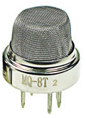
The MQ-8 can be obtained very cheaply, just a few bucks. A good place to look for it is on ebay, which always has auctions on them for the $2-$3 range.
Important, it is recommended that you do not obtain the standalone sensor but the whole MQ-8 board. This is because if you buy the standalone sensor, you will have to finish building the whole schematic before you can connect it to the arduino. So that less work is required for integrating it with the arduino, it is recommended that you buy the complete MQ-8 sensor circuit. This you can see below.
If you buy the complete board, there are 4 leads which need to be connected.
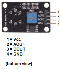
There 4 leads are Vcc, AOUT, DOUT, and GND.
The Vcc and GND leads establishes power for the hydrogen sensor.
The other 2 leads are AOUT (analog output) and DOUT (digital output).
How the sensor works is
the terminal AOUT gives an
analog voltage output in proportion to the amount of methane the sensor detects. The more methane it detects, the greater the analog voltage
it will output. Conversely, the less CO it detects, the less analog voltage it will output. If the analog voltage
reaches a certain threshold, it will send the digital pin DOUT high. Once this DOUT pin goes high, the arduino will detect
this and will trigger the LED to turn on, signaling that the methane threshold has been reached and is now over the limit. How you can change this
threshold level is by adjusting the potentiometer to either
raise or lower the level.
MQ-8 Hydrogen Gas Sensor Circuit Schematic
The hydrogen gas sensor circuit we will build with an MQ-8 sensor integrated with an arduino is shown below.
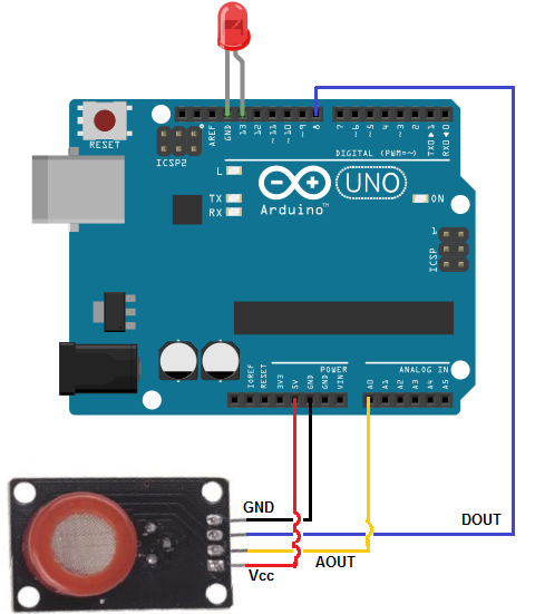
The connections are pretty basic.
To connect the sensor, there are 4 leads. 2 of them are for power. The Vcc terminal of the sensor connects into the 5V terminal of the arduino board. The GND terminal of the sensor connects into the GND terminal of the arduino. This establishes power for the sensor.
The other 2 connections are the analog and digital output of the sensor. These connect to analog pin A0 and digital pin D8, respectively.
Code
The code which we need to upload to the arduino so that it can measure hydrogen gas levels is shown below.
const int AOUTpin=0;
const int DOUTpin=8;
const int ledPin=13;
int limit;
int value;
void setup() {
Serial.begin(115200);
pinMode(DOUTpin, INPUT);
pinMode(ledPin, OUTPUT);
}
void loop()
{
value= analogRead(AOUTpin);
limit= digitalRead(DOUTpin);
Serial.print("Hydrogen value: ");
Serial.println(value);
Serial.print("Limit: ");
Serial.print(limit);
delay(100);
if (limit == HIGH){
digitalWrite(ledPin, HIGH);
}
else{
digitalWrite(ledPin, LOW);
}
}
The first block of code defines all the pin connections of the sensor and the LED. Since the AOUTpin connects to analog pin A0, it is initialized to 0. Since the DOUTpin connects to digital pin D8, it is initialized to 8. Since the LED connects to digital pin D13, it is initialized to 13. 2 variables, limit and value, are also declared. These will be used to store the value of the analog pin AOUT and digital pin DOUT.
The next block of code sets the baud rate and declares the DOUTpin as input and the ledPin as output. This is because the sensor is an input to the arduino for the arduino to read and process the sensor value. And the LED is an output will serves an indicator if the sensor has detected hydrogen.
The next block of code reads the sensor pin AOUT and stores the value in the integer value. It also reads the sensor pin DOUT and stores the value in the integer limit. We then print the hydrogen value, which will be a numeric value ranging from either 0 (no hydrogen detected) to 1023 (maximum level of hydrogen that can be read). We will aslo print the limit which will either be HIGH or LOW. If the hydrogen detected is under the threshold level, the value of limit returned will be low. If the hydrogen detected is above the threshold, the value of limit returned will be HIGH.
If the value is HIGH, the LED will turn on. If the value is low, the LED will remain off.
Related Resources
How to Use the LM741 Op Amp as a Comparator
How to Build an LM339 Quad Voltage Comparator Circuit
How to Build a Dark-activated Switch
How to Build a Hall Effect Sensor Circuit
How to Build a Touch Sensor Circuit
How to Build an Accelerometer Circuit
How to Build a Motion Detector Circuit
How to Build a Motion Detector Alarm Circuit