
How to Build a 555 Timer Bistable Circuit
In this circuit, we will show how to build a bistable circuit using a 555 timer chip.
A bistable circuit is a circuit that can be in 1 of 2 stable states. It can either be LOw for an indefinite period of time or it can be HIGH or an indefinite period of time.
By an indefinite time, it is meant that the 555 timer can hold an output at either the HIGH or LOW state forever unless externally switched to the other state.
So a bistable mode can hold either of the 2 states, HIGH or LOW, stable, meaning unchanged forever unless it is desired that a switch of status be implemented.
The other 2 modes that a 555 timer can be in is astable mode and monostable mode.
Astable mode acts like a square wave generator. The output from the 555 timer in astable move switches from HIGH to LOW, HIGH to LOW, HIGH to LOW, indefinitely. Because the output doesn't hold either state but undulates back and forth between HIGH and LOW, it is said to be in astable mode, which means lacking a stable mode.
Monostable mode is called a one-shot state. It is a state in which a single pulse is sent to output when the 555 timer's trigger pin is triggered. With a single pulse lasting only a certain duration, an output turns HIGH for the duration of the pulse and then shuts off.
A bistable mode is unique in that it can hold either state indefinitely. Thus, if you want to the circuit to be HIGH for a period of time and LOw for a period of time, a bistable circuit can easily accomplish. This circuit is good for manual control when we desire the circuit sometimes to be in a HIGH state or at other times to be in a LOW state.
So we will demonstrate this 555 timer bistable circuit with an LED as the output device. Using 2 pushbuttons, one which controls the output being HIGH and the output which controls the output being LOW, we can control output states.
This circuit functions similarly to a flip flop, which is a bistable device that can hold either 1 of 2 states indefinitely.
Components Needed
- 555 Timer Chip
- 2 10KΩ resistors
- 10nF ceramic capcaitor
- 2 pushbuttons
- 470Ω resistor
- LED
The 555 timer can be obtained very cheaply from pretty much any electronic retailer.
The 555 timer is an 8-pin chip.
If you want to know all the pinout of the 555 timer, what each pin is and what each pin does, see 555 Timer Pinout.
In this circuit, we will connect the 555 timer to be in bistable mode.
In this mode, the 555 timer can either be in the HIGH or LOW state indefinitely.
The connections are shown below.
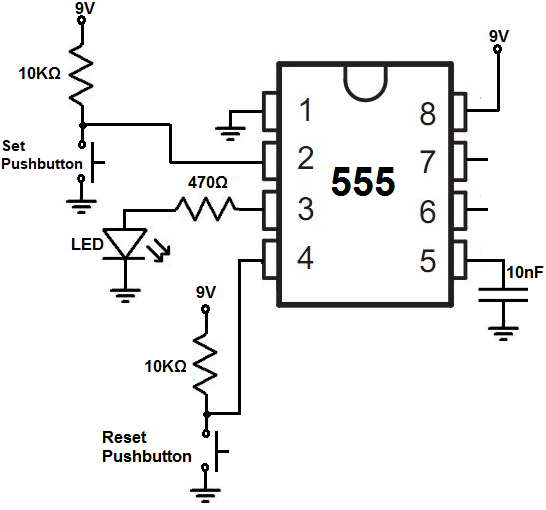
555 Timer Bistable Circuit
The bistable circuit that we will build using a 555 timer is shown below.
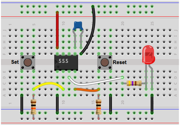
The breadboard schematic of the above circuit is shown below.
The circuit operates on 9VDC of power. So the power line is 9V.
Pin 8, which is the power supply pin, VCC, gets connected to +9VDC. Pin 1, which is power ground, gets connected to ground. This establishes sufficient power to the chip for this circuit.
This 555 timer is in bistable mode.
Bistable mode can have 2 stable states. When the the pushbutton connected to pin 2 is pressed, the 555 timer output goes to a HIGH state. When the pushbutton connected to pin 4 is pressed, the 555 timer outputs goes to a LOW state.
The 555 timer in bistable mode works off of the trigger pin and reset pins of the 555 timer.
There are 2 pushbuttons in this circuit.
The first pushbutton is connected to pin 2, which is the trigger pin of the 555 timer. One end of the pushbutton is connected to ground. The other end is connected to +9V via a 10KΩ resistor. This resistor functions as a pull-up resistor. The pin of the 555 timer is connected to the +9V terminal end via the 10KΩ resistor. Therefore, when the pushbutton is unpressed, the pin is normally HIGH.
The trigger pin is an active LOW pin. Therefore, it does not turn the output HIGH unless the trigger pin is LOW. Being that when unpressed, the trigger pin is HIGH, the output stays LOW under this condition. Now when we push the pushbutton, the pin is now in contact with ground. The voltage that the pin now reads drops dramatically and is now at a LOW state. Being in a LOW state now, the trigger pin is triggered, which turns the output HIGH.
Thus, when the pushbutton at pin 2 is connected, the output is now HIGH, which turns on the LED. The HIGH state is now the 555 timer's stable output. It stays HIGH indefinitely- unless the power to the circuit is shut off, or we let go of the press or the reset pushbutton is pressed.
That brings us to the other pushbutton.
The other pushbutton is connected to pin 4. Pin 4 is the reset pin of the 555 timer.
Just like pin 2, pin 4 is connected to +9V via a 10KΩ, which functions a pull-up resistor to the positive voltage. One end of the pushbutton connects to +9V; the other end is connected to ground. The +9V end is connected to the pin 4. Thus, pin 4, when the pushbutton is unpressed, is normally connected to +9V. Thus, pin 4 is normally.
Just like pin 2, the trigger pin, pin 4, the reset pin, is an active LOW pin. Therefore, in order to active the pin, the voltage connected to it must be in a LOW state, which is less than 1/3 of the supply voltage.
Being that when the pushbutton is unpressed, pin 4 is connected to +9V, the reset function of the pin isn't triggered. Thus, the output will not be turned (if it is HIGH) when the pushbutton is unpressed.
Now when we press the pushbutton, the pin comes in contact with ground. The voltage falls dramatically to less than 1/3 of the supply voltage and the reset function is activated. If the output was HIGH, it now turns LOW. And the output will stay LOW indefinitely while we hold this push.
And this is how bistable mode of a 555 timer works. Using the pushbuttons, we can switch to either state, HIGH or LOW, for an indefinite period of time. A bistable switch allows either state to be stably kept.
It's probably better to use toggle switches rather than pushbuttons because toggle switches can hold the state for you, unlike pushbuttons that you must keep held.
You can make this determination.
To see how this circuit works in real life, please see the video below.
Related Resources
How to Build an LED Flasher Circuit with a 555 Timer Chip
How to Build a Clock Circuit with a 555 timer
How to Build a 555 Timer Delay Before Turn On Circuit
How to Build a 555 Timer Delay Before Turn Off Circuit
How to Build a Sine Wave Generator with a 555 Timer Chip
How to Build a Triangle Wave Generator Circuit with a 555 Timer
How to Build a Voltage-controlled Oscillator with a 555 Timer Chip