
How to Build a Triangle Wave Generator Circuit
In this project, we will show how to build a triangle wave generator circuit using a 555 timer chip.
A triangle wave generator circuit is a circuit that produces a triangular waveform, as shown above.
We have also built a triangle wave generator circuit with an LM741 op amp.
Triangle waves are often present in function generators, which is a device that can produce waveforms of all different sorts. Function generators produce waveforms such as sine waves, square waves, and triangular waves. Other waveforms include ramp, pulse, ExRise, ExpFall, Sinc, Noise and DC. Advanced function generators can produce arbitrary waveforms in which you can create basically any type of waveform possible using a variety of math functions.
In this circuit, though, we set out to build a triangle wave generator.
We do this by first creating a square wave with the 555 timer chip, which is pretty simple to do. We then take that square wave and convert it into a triangle wave via RC networks, also called pole filters.
So, besides the 555 timer chip, all we need are resistors and capacitors to build our circuit.
We will show how you can adjust both amplitude and frequency of the triangle waveform so that you can adjust it
to the amplitude and frequency that you want.
Components Needed
- 555 timer chip
- 10KΩ resistor
- 68KΩ resistor
- 2 1.5KΩ resistor
- 1nF ceramic capacitor
- 2 10nF ceramic capacitors
- 100nF ceramic capacitor
The 555 timer is a versalite IC which can serve many, many functions.
In this circuit, we will use it to produce a square waveform signal from its output.
If you want to know all the pinout of the 555 timer, what each pin is and what each pin does, see 555 Timer Pinout.
In this circuit, we will connect the 555 timer to be in astable mode.
In this mode, the 555 timer will go from HIGH to LOW, HIGH to LOW, HIGH to LOW, mimicking a digital square waveform.
The connections are shown below.
Apart from that, the only other components we use are resistors and capacitors.
Triangle Wave Generator Circuit
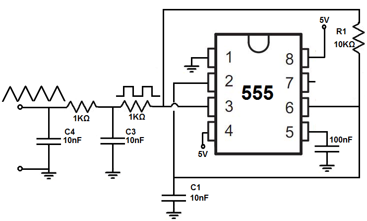
The triangle wave generator circuit that we will build with the 555 timer circuit is shown below.
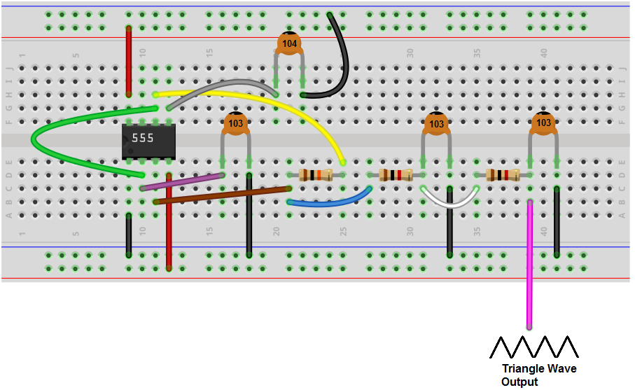
The breadboard circuit of the circuit above is shown below.
First and foremost, we use 5VDC of power for this circuit.
This circuit is composed of really 2 main subparts that make up the whole circuit.
The first part is the 555 timer circuit which produces a square wave signal of about 10KHz.
The second part of the circuit is then taking the square wave which the 555 timer produces and converting it into a triangle wave. This we do with a 2-pole filter, which are 2 resistors filters, each composed of 1 resistor and 1 capacitor.
First, we'll discuss the first part and then the second.
So in the first part, we first need to generate a square wave with the 555 timer. This is done with the circuit above, which puts the 555 timer in astable mode. Astable mode means that the waveform that the 555 timer produces is neither in a HIGH state continouously or a LOW state continuously, but keeps on flipping from LOW to HIGH, LOW to HIGH, over and over again. This is why it's called astable, since it's state isn't stable and always changing from one to the other.
The R1 resistor and C1 capacitor determine the frequency of the square wave signal output. By adjusting these values, we can adjust the frequency of the output signal from the circuit.
For this circuit, with the values given above, the frequency of the output signal will be about 6KHz.
This comes out from the output pin, pin 3, of the 555 timer. Again, this is a square wave.
Now once we have reached this point, this starts the next part of our circuit, which converts the square wave to a triangle wave. This is done through RC networks. The RC networks reshape the waveform to a triangular shape. This circuit uses 2 RC networks. Both RC networks are the same values for the resistors and capacitors.
The first capacitor creates the classic capacitor charging waveform. If you were to place an oscilloscope on the first capacitor, then you would see an upside down parabolic curve as the capacitor is charged up. As it discharges, you would see an upright parabolic curve. This is what the first capacitor produces.
The signal then passes through the second capacitor. This exponentially shaped function now gets converted into a triangle waveform. So as the second capacitor charges up, there is a straight line up with increasing slope. And as the capacitor discharges, there is a straight line down with decreasing slope. So this is what you would see if you place the probe of an oscillator on the second capacitor.
Be aware that this circuit is very frequency dependent. It will not work for any AC signals of any frequency. You will have to adjust the capacitors C3 and C4 when there are changes to the input frequency signal. The rule of thumb is that as the frequency increases, you will need capacitor values of lesser capacitance. As the frequency decreases, you will need capacitor values of greater capacitance. Swap out both capacitors at the same time to the same values when doing this circuit, because you want the AC signal to respond equally to both capacitors. Being that the frequency of the signal has to respond to both capacitors, you want them to be of the same value that works with the frequency of the AC signal.
As far as amplitude adjusting goes, being that the 555 timer can operate with as much as 16V, 16V can be used as the maximum range as the amplitude. So if you want to increase the signal, the 555 timer can take in as much as 16V. On the lower end, it can operate off of power as low as 4.5V. So this is the voltage range that can be used for this circuit.
And this is how a triangle wave generator circuit can be built with a 555 timer and resistors and capacitors.
To see how this circuit works in real life, please see the video below.
Related Resources
How to Build a Square-to-Triangle Wave Converter Circuit
How to Build a Square-to-Sine Wave Converter Circuit
How to Build a Clock Circuit with a 555 timer
How to Build an Astable Multivibrator Circuit with Transistors
How to Build a Multivibrator Circuit with a 4047 chip (for astable mode operation)
How to Build a Voltage-Controlled Oscillator Circuit with a 4046 Chip
How to Build an Oscillator Circuit with a 7414 Schmitt Trigger Inverter Chip
How to Build a Sine Wave Generator Circuit with a 555 Timer
How to Build a Ramp Generator with Transistors
How to Build a Voltage-controlled Oscillator with a 555 Timer Chip