
How to Build a 555 Timer Monostable Circuit
In this circuit, we will show how to build a 555 timer monostable circuit.
When a 555 timer is in monostable mode, when the 555 timer is triggered, a single high pulse is released, turning on the output for a certain period of time. Once this HIGH period of the pulse has passed, the output turns off and stays off- unless the pushbutton is pressed again.
The reason this is called the monostable state is because there is only one stable output state unless there is a trigger. The one stable state is OFF. The signal feeding the output is normally LOW. The only time it is HIGH is when we press the pushbutton, triggering a single pulse.
The signal that is triggered will resemble that which is shown below.
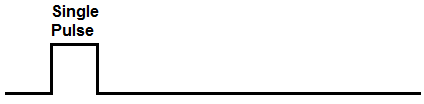
So you can see based on this signal, there is a single pulse. This is when we press down on the pushbutton. This sends a trigger signal to the 555 timer. This trigger signal creates that single pulse. After the period of time of the pulse has elapsed, the signal goes back to a LOW state, which is the only stable state it has. It will stay at this LOW state, until the pushbutton is pressed again and another single pulse is created before going LOW again.
This circuit lends itself well to conditions where the output needs to be on only for brief periods of time and be user-operated, as this circuit lends itself well to pushbuttons.
This circuit is actually great for demonstration purposes because a user can press the button, see the operation of the circuit, with the circuit automatically turning to the OFF state on its own.
In this circuit, we will use an LED as our output device. So when the circuit is triggered, the LED will turn on for a few seconds and then turns off.
We will show also how you can vary the duration of the pulse, so that the output device which you are turning on can be on for different periods of time.
Components
- 555 Timer Chip
- 2 10KΩ resistors
- 220μF capacitor
- 470Ω resistor
- LED
The 555 timer can be obtained very cheaply from pretty much any electronic retailer.
The 555 timer is an 8-pin chip.
If you want to know all the pinout of the 555 timer, what each pin is and what each pin does, see 555 Timer Pinout.
In this circuit, we will connect the 555 timer to be in monostable mode.
In this mode, the 555 timer will produe a single pulse when triggered.
The connections are shown below.
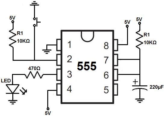
555 Timer Monostable Circuit
The monostable circuit that we will build using a 555 timer is shown below.
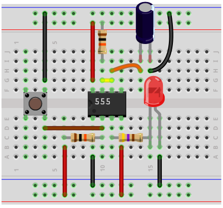
The breadboard schematic of the above circuit is shown below.
The circuit operates on 9VDC of power. So the power line is 9V.
Pin 8, which is the power supply pin, VCC, gets connected to +9VDC. Pin 1, which is power ground, gets connected to ground. This establishes sufficient power to the chip for this circuit.
This 555 timer is in monostable mode.
Monostable mode produces a single pulse of adjustable duration during a pushbutton press.
Pin 2, the trigger pin, is one of the focal pins of this chip. This is how the 555 timer gets triggered to create that single pulse. Once a trigger is sent to this pin, the 555 timer output temporarily gets taken out of its stable state, which is the LOW state, and goes temporarily to its unstable state, which is the HIGH state. This creates the single pulse that you see on the output.
In order for pin to work, we first connect a 10KΩ resistor to 5V. Then in parallel to this resistor, we connect a pushbutton. One end of the pushbutton button connects to the pin 2 terminal and the other end of the pushbutton connects to ground.
Pin 2 of the 555 timer is an active low trigger. This means that this pin is only activated when the voltage being fed into is LOW, or less than 1/3 of the supply voltage. Since we are supplying the 555 timer with 9VDC, once the voltage at this pin gets to 3V or lower, this pins activates. When the 555 timer is triggered via pin 2, the output at pin 3 goes HIGH.
So during operation, while the pushbutton is unpressed, pin 2 is connected to +5V via the resistor. So the pin 2 reads a HIGH value. So it's connected HIGH. In this HIGH state, the pin is not triggered, because again the pin is active LOW.
Now when we press down on the pushbutton, now pin 2 has direct contact with ground. The voltage drops dramatically well below 1/3 of the power supply voltage. Thus, a trigger is activated. This lets the output pin, pin 3, go HIGH.
And this is the principle behind a 555 timer monostable circuit.
Once the trigger pin is activated, a brief HIGH pulse is created at pin 3. This, again, is a single pulse that is not repeated unless another trigger is created- by pushing down again on the pushbutton.
Pin 3 is the output pin. To this pin, we attach the output that we want to be turned on. In the case of this circuit, we connect an LED along with a current-limiting resistor, as to not burn out the LED.
Pin 4 is the reset pin. Being that we aren't using it for this circuit, we simply connect to +5V. The reset pin is active LOW, which means it turns on when the voltage fed to it is LOW. Thus, in order to inactivate it, we simply permanently connect it to the positive voltage.
Pin 5, the control voltage, is not needed for this cirucit and is not unused.
Pin 6 and pin 7 control the time interval of the duration of the pulse monostable pulse created. The resistor and capacitor values used create an RC network. The value, τ= RC, forms the time constant for how long the pulse will last. Thus, if you use a greater resistor and capacitor value, this will increase the time constant of the signal, thus making the duration of the pulse longer or greater. If you want the pulse to be shorter, which makes the output on for a shorter period of time, you want to use smaller values for the resistor and capacitor. So this is by adjusting the resistor and capacitor values, we can adjust how long the output is on for when the 555 timer is triggered.
And this is a basic monostable circuit built with
a 555 timer chip.
To see how this circuit works in real life, please see the video below.
Related Resources
How to Build an LED Flasher Circuit with a 555 Timer Chip
How to Build a Clock Circuit with a 555 timer
How to Build a 555 Timer Delay Before Turn On Circuit
How to Build a 555 Timer Delay Before Turn Off Circuit
How to Build a Sine Wave Generator with a 555 Timer Chip
How to Build a Triangle Wave Generator Circuit with a 555 Timer
How to Build a Voltage-controlled Oscillator with a 555 Timer Chip