
How to Build an AND gate from NAND Gates
A NAND gate is a truly versatile logic gate.
It is referred to as the universal logic gate chip. This is because any other logic gate on the planet can be made from the right combination of NAND gates. NAND gates can build them all.
Now we will go over how to build an AND gate from NAND gates.
And to do so turns out to be really simple.
Since a NAND gate is really an AND gate followed a NOT gate, all you have to do to turn it into an AND gate is to add a NOT gate to it. This inverts the NAND gate back into an AND gate.
We'll show how all this is done.
We're going to use a 4011 NAND gate chip to build this circuit.
Components Needed
- 4011 NAND gate chip
- 330Ω resistor
- LED
- Jumper Wires
The 4011 quad NAND gate chip can be obtained very cheaply from a number of online retailers for just a few cents. One place it can be obtained from is Tayda Electronics at the following link: Tayda Electronics- 4011 Quad 2-Input NAND Gate IC. However, it is a very popular chip and many electronics parts suppliers have them.
To find out the pinout and how to connect this chip, see How to Build a NAND
Gate Circuit Using a 4011 Chip.
AND Gate Circuit from NAND Gate Conceptually
A 4011 is a quad NAND gate chip. This means it contains 4 NAND gates inside of it. To build an AND gate from a NAND gate, we simply need to use 2 of the 4 gates that a 4011 NAND chip offers.
Conceptually, the AND gate is built from NAND gates through the following diagram.
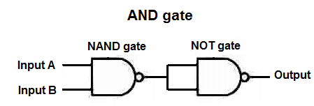
2 inputs are fed into the first NAND gate. The output of this NAND gate is fed into a second NAND gate whose inputs are tied together. The second NAND gate functions logically just like a NOT gate. According to NAND gate logic, when 2 inputs are LOW (0), a HIGH output (1) is produced. When 2 inputs are HIGH, a LOW output (0) is produced. This perfectly simulates a NOT gate.
A NAND gate followed by a NOT gate is equivalent to an AND gate.
AND Gate Circuit from NAND Gate Conceptually
The circuit schematic for an AND gate from a 4011 NAND gate chip is shown below.
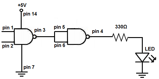
Basically, we use the first gate of the 4011 as the gate where we have our inputs. We feed the output of this gate, which is pin 3, into the input of the second gate, which has shares a common signal because they're tied together. This second gate serves as a NOT gate. In NAND logic, 2 LOWs (0) produce a logic HIGH (1) and 2 HIGHs (1) produce a logic LOW (0). Therefore, if we tie both inputs together, as we do, the NAND gate functions logically just as a NOT gate.
The output of this second gate is our output, which will have the same logical values as an AND gate.
Below is the breadboard schematic of the circuit above.

The cyan and white wires represent the inputs to the NAND gate.
The output is connected to an LED along with a 330Ω current-limiting resistor. Following AND gate logic, it will only light up when both inputs are HIGH (greater than 2.5V).
Related Resources
How to Build a Diode AND Gate Circuit
How to Build a Diode OR Gate Circuit
How to Build a Logic Probe
How to Build a Light Detector Circuit with a NAND Gate Chip
How to Build a Night Light Circuit with a NAND Gate Chip
How to Build a NAND Gate Circuit Using a 4011 Chip