
How to Build an AVR Blinking LED Circuit
In this project, we will build an LED blinking circuit with an AVR chip.
This is a circuit in which an LED will blink on and off, on and off, on and off, repeatedly, forever until stopped by the user such as by shutting it off.
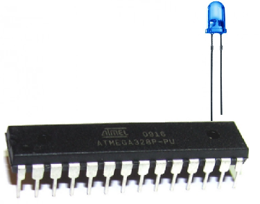
As with pretty much all the AVR projects we do, we will use the popular ATmega328 chip.
This chip is completely compatible with the ATmega168 chip, so that chip can be used as well. All the pins (the pin layout) are exactly the same.
Our circuit will be very simple. We will blink a single LED on and off. It will be on for a second, then shut off for a second, then turn back on for a second, then shut off for a second, and repeat this seemingly forever.
Of course you can adjust the time interval but 1 second is pretty standard. If you make the period of time too long, then it won't be a blinker. If you make the period of time too short, the human eye may not be able to detect the LED turns on and off. It may seem like it's just on. Therefore, 1 second is reasonable. But again, this can be easily and simply adjusted by changing the time delay, which you will see how to do in the code below.
Components Needed
- Atmega328/168 Chip
- LED
- 330Ω resistor
- 0.1μF ceramic capacitor
- AVR Programmer
This is a basic circuit which requires only a few basic components.
At the heart of the circuit, of course, is our AVR chip. We will use either an Atmega168 or an Atmega328 chip. Both have the same pin layouts. The only difference is that the Atmega328 has more SRAM and flash memory. But for this basic circuit, these upgrades are negligible, as both upgrades are not warranted by such a simple program.
If you need a reference for the pinout of the Atmega328 chip to gain more familiarity with what each pin does, see Atmega328 Pinout. You'll need to be familiar with what each pin does in order to really know how to connect up this circuit meaningfully.
And apart from the AVR chip, all we need is the LED which we're going to blink and the resistor which will be in series with the LED to limit current going to the LED so it doesn't overload (with current) and burn out.
Then we'll just need an AVR programmer, such as a USBASP, so that we can upload our program to the flash
memory of the AVR and run it.
AVR Blinking LED Circuit Schematic
The schematic diagram of the AVR Blinking LED Circuit is shown below.
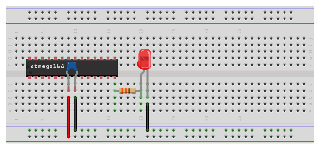
Again, it's a very basic circuit.
First, we need power, as all AVR circuits do. About 5 volts of power is sufficient for operation of the AVR chip. You can get this either from batteries or a DC power supply. Vcc is pin 7 and GND is pin 8. Therefore, we connect +5V of power to pin 7 and connect pin 8 to ground on the breadboard. In between both pins, we place a 0.1μF ceramic capacitor to smooth out the power of the power supply so that the AVR chip gets a smooth power line.
We connect the anode of our LED to AVR pin PB0. This is pin 14 of the AVR. Since it is an LED, we want to limit current flowing to the LED so it doesn't burn out. This is why we place a 330Ω resistor in series with the LED. The cathode of the LED gets connected to ground.
These are all the connections necessary to light up the LED.
Code
Now that the hardware is setup, all we need is the software to get the LED blinking.
The code for the LED blinker circuit is shown below.
#include <avr/io.h>
#include <util/delay.h>
int main(void) {
DDRB |= (1 << PB0);
while (1) {
PORTB= 0b00000001;
_delay_ms(1000);
PORTB= 0b00000000;
_delay_ms(1000);
}
return (0);
}
In our code, we first include the preamble, which is where we put our include information from other files, which defines global variables and functions. If you're going to be using a library of functions from some other source code, or just reusing your own code, this is where you'll do it.
After the preamble comes the main() function. The main() function is unique and set apart from all other functions. Every C program must have exactly one main() function. main is where the AVR starts executing your code when the power first goes on, so it's the entry point of the program. In this function in our program, we first set the PORT B as output. We do this by by writing a 1 to the Data Direction Register B, DDRB. The Data Direction Register B allows us to make the bits of register B input or output. Writing a 1 makes them output, while a 0 would make them input. Being that we are attaching an LED to act as output, we write a 1, making the PORT B pins output.
The next line of code includes a while(1) statement, which is a loop, often referred to as the main loop or event loop. This line is always true; therefore, it executes over and over and over again in an infinite loop. It never ceases. Therefore, in our code, the LED will blink on and off, on and off, on and off, unless power is shut off from the AVR or the code is erased from program memory.
The first line, PORTB= 0b00000001;, gives a 1 to the PB0 of PortB. Remember, PORTB is a hardware register on the AVR chip that contains 8 pins, PB7-PB0, going from left to right. Putting a 1 at the end gives a 1 to PB0; this sets PB0 high which turns it on. Therefore, the LED attached to pin PB0 will turn on and light up. After this, we create a 1-second delay, so that the LED turns and stays on for exactly 1 second. It then shuts off, by the line, PORTB= 0b00000000; This line turns off all 8 Port B pins, so that even PB0 is off, so the LED turns off. It turns off exactly for 1 second, before starting the loop all over again and encountering the line, PORTB= 0b00000001;, which turns it back on, repeating the process all over. This happens infinitely so that the LED constantly blinks on and off.
The last line of our code is a return(0) statement. Even though this code is never executed, because there is
an infinite loop which never ends, for our programs that run on desktop computesr, it's important for the operating system
to know whether they ran correctly or not. For that reason, GCC, our compiler, wants every main() to end with a return code.
Return codes are needless for AVR code, which runs freestanding of any supporting operating system; nevertheless, the compiler
will raise a warning if you don't end main with return(). It's best to take compiler warnings seriously, since they can
help debug issues many times. The only other way to avoid return() statements would be to prototype the main function like the following
before you define it: void main(void)_attribute_((noreturn)); but it's probably easier just to put a return statement at
in the end, which is what we've done in our code.
And this is how we can create a blinking LED circuit with an AVR.
Related Resources
How to Use the LM741 Op Amp as a Comparator
How to Build an LM339 Quad Voltage Comparator Circuit
How to Build a Dark-activated Switch
How to Build a Hall Effect Sensor Circuit
How to Build a Touch Sensor Circuit
How to Build an Accelerometer Circuit
How to Build a Motion Detector Circuit
How to Build a Motion Detector Alarm Circuit