How to Build an AVR Night Light Circuit
In this project, we will build a night light circuit with an AVR chip. This is a circuit in which an LED will turn on whenever it gets dark.
This circuit will be automatic in nature, turning on the LED light, as soon as it gets dark below a certain level.
Night light circuits are very common household devices sold majorly at big retailers such as home improvement stores and discount household item stores.
The component that we will use that is able to sense light is a photoresistor. With a photoresistor, the circuit can know the amount of light in a given environment. This is because a photoresistor's resistance changes in proportion to the amount of light it is exposed to. When exposed to bright light, a photoresistor has very low resistance. When exposed to darkness, a photoresistor has a very high resistance. According to ohm's law, the amount of voltage that falls across a component is directly proportional to its resistance value, according to the formula, V= IR. Thus, the more resistance a component has, the more voltage will fall across it. The less resistance a component has, the less voltage that will fall across it. Thus, when the photoresistor is exposed to bright light and has low resistance, it will carry a small voltage across it. When exposed to darkness and has very high resistance, it will carry a high amount of voltage. Being that the AVR chip can detect and measure voltage, it can read whether the photoresistor is exposed to bright light conditions or darkness. When exposed to darkness, we will write code so that the LED connected to the AVR turns on.
For this circuit to work, we will place the photoresistor in a voltage divider circuit with a fixed resistor. We will carefully choose the resistor value so that the resistor's resistance value is midway between the light resistance value of the photoresistor and the dark resistance value. (The light resistance value is the resistance value when the photoresistor is exposed to bright light and the dark resistance value is the resistance value when the photoresistor is exposed to complete darkness). For this circuit, I will be using a GL5537 photoresistor, which has a light resistance of 20-30KΩ and a dark resistance of 2MΩ. Therefore, a resistor such as a 100KΩ resistor will work perfectly. When the photoresistor is exposed to bright light, its resistance will be about 20KΩ. In a voltage divider circuit 5V as the voltage source, 1V will fall across the photoresistor and the remaining 4V will fall across the 100KΩ fixed resistor. Now in dark conditions, 4.95V will fall across the photoresistor and about 0.05V will fall across the fixed resistor. This type of drastic voltage allocation difference can easily be detected by the AVR. When most of the voltage falls across the photoresistor and the AVR detects this voltage level, it can easily know that the photoresistor is exposed to darkness. When it detects this high level of voltage, we will make it so that in our code, we turn on the LED.
And this is how an AVR chip can function as a night light circuit.
Components Needed
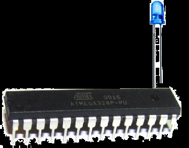
- Atmega328/168 Chip
- GL5537 Photoresistor
- LED
- 330Ω resistor
- 0.1μF ceramic capacitor
- AVR Programmer
The AVR chip we will use is either the Atmega168 or Atmega328 chip. Both have the same pin layouts. If you need a reference for the pinout of the AVR chip to gain more familiarity with what each pin does, see Atmega328 Pinout. You'll need to be familiar with what each pin does in order to really know how to connect up this circuit meaningfully.
Apart from the AVR chip, we need a photoresistor. The type that we will use in this circuit is the GL5537 photoresistor. This, again, has a light resistance of about 20-30KΩ and a dark resistance of about 2MΩ. If you are going to use another photoresistor, just know its light and dark resistance and figure out the calculations necessary of how voltage will be divided up in the voltage divider circuit. You will need certain values, that we'll explain below, to go in our code so that we can program the AVR to respond to light and dark conditions, based on these value numbers.
The other components we need are the LED and the 330Ω resistor in series to limit current to the LED so that it
doesn't burn out. We need a ceramic capacitor between the AVR's power pins to smooth out the power supply voltage going to the
AVR. And we need an AVR programmer to upload our code to the AVR so that it can run it.
AVR Night Light Circuit
The schematic diagram of the AVR night light circuit is shown below.
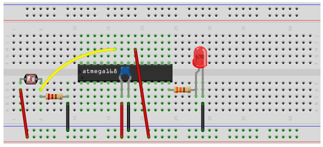
This circuit is pretty baisc.
First, we need power, as all AVR circuits do. About 5 volts of power is sufficient for operation of the AVR chip. You can get this either from batteries or a DC power supply. Vcc is pin 7 and GND is pin 8. Therefore, we connect +5V of power to pin 7 and connect pin 8 to ground on the breadboard. In between both pins, we place a 0.1μF ceramic capacitor to smooth out the power of the power supply so that the AVR chip gets a smooth power line.
Next, we have our voltage divider circuit. The end lead containing the photoresistor gets connect to the positive voltage rail and the other end lead containing the fixed resistor gets connected into the ground rail. In between these 2 components, we place a jumper wire and connect it to PC0 (pin 23) of the AVR chip. Pins PC0 to PC5 of the AVR are the analog input pins. There are 6 analog input pins in total. Being that the photoresistor is an analog component (it offers a multitude of values), it must be connected to an analog input pin of the AVR chip. With this jumper wire connected to analog pin PC0, the AVR can measure the amount of voltage that drops across the photoresistor in the voltage divider circuit. If the voltage is below the threshold level we will set at 3.5V, then this means that the photoresistor is exposed to sufficient lighting, and the LED will not be programmed to turn on. If the voltage is above 3.5V, then the photoresistor is exposed to dark conditions, and the LED will be made to turn on.
The only other connection we make in our hardware circuit schematic is tying AVCC to VCC. AVCC is the power supply for the analog-to-digital converter inside the AVR chip. Without its own power supply, the ADC can't function. It needs its own power source in order to operate. Therefore, we must connect it to VCC for the ADC to work. Without it, we won't be able to measure analog signals because the ADC is necessary to convert the analog signal to a digital signal, which is the only type of signal that the AVR can interpret. Therefore, you can see why tying it to AVCC is the only way an analog circuit can work.
The reason we don't have to ground the ground wire of the ADC is because both grounds on the AVR chip. So being that one GND terminal is already connected to ground, we don't have to ground the ADC ground.
And the reason we don't have to tie AREF to anything is because in our software, we connect make it so that AVCC and AREF are internally connected. Therefore, AREF will be AVCC.
These are all the connections necessary for this AVR night light circuit.
Code
Now we just need the software in order to get our circuit up and going.
The code for the AVR potentiometer circuit is shown below.
#include <avr/io.h>
#include <util/delay.h>
static inline void initADC0(void) {
ADMUX |= (1 << REFS0);
ADCSRA |= (1 << ADPS1) | (1 << ADPS0);
ADCSRA |= (1 << ADEN);
}
int main(void) {
uint16_t photoresistorValue;
uint16_t threshold_level;
threshold_level= 0b1011001100;
DDRB |= (1 << PB0);
initADC0();
while (1) {
ADCSRA |= (1 << ADSC);
loop_until_bit_is_clear(ADCSRA, ADSC);
photoresistorValue= ADC;
if (photoresistorValue > threshold_level) {
PORTB= 0b00000001;
}
else {br>
PORTB= 0b00000000;
}
return (0);
}
}
So we first import libraries to our files. This is because this libraries contain definitions or functions we use in our code.
Next, we write code for the initialization of our ADC. We set the reference voltage to AVCC, we set the ADC clock prescaler to 1/8 of the clock speed, and we enable the ADC. All of this ADC initialization is done in code.
Next, we create 2 16-bit variables, photoresistorValue and threshold_level. Since the ADC is 10-bit ADC, meaning it holds 10 value places, the variable to hold this
10-bit ADC value must be in a 16-bit register, not an 8-bit register. We then initialize the threshold_level to 716. This is because we will set the threshold level to be 3.5V. If the voltage is below
3.5V, this means the photoresistor is exposed to sufficient lighting, and the LED should not turn on. If the voltage is above 3.5V, then it is exposed to dark lighting conditions. 3.5V is 70% or
0.7 of the 5V supplying the voltage divider circuit. Being that a voltage of 0V translates into an ADC value of 0 and a voltage of 5V translates into an ADC value of 1023, a voltage of 3.5V will
translate into an ADC value of 716 (0.7 * 1023= 716). Therefore, 716 is our ADC threshold value. This is a binary value of 0b1011001100. If below this level, the LED will be off. If above this level,
the LED will turn on. And this is basically how the AVR night light circuit works.
Related Resources
How to Use the LM741 Op Amp as a Comparator
How to Build an LM339 Quad Voltage Comparator Circuit
How to Build a Dark-activated Switch
How to Build a Hall Effect Sensor Circuit
How to Build a Touch Sensor Circuit
How to Build an Accelerometer Circuit
How to Build a Motion Detector Circuit
How to Build a Motion Detector Alarm Circuit