
How to Build an AVR Potentiometer Circuit
In this project, we will build a potentiometer circuit with an AVR so that the AVR can read the voltage value that the potentiometer is producing.
Thus, the potentiometer functions as a resistive sensor.
Based on the value that we obtain from the potentiometer, we can make any type of circuit actions, such as light an LED if the voltage goes above 2.5V or above 3V or turn on any device if the voltage is above or below or at a certain level.
A potentiometer is an analog device. It offers resistance anywhere from nearly 0Ω to its rated resistance value. Voltage gets allocated, according to Ohm's Law, proportionally according to the resistance a component offers. The formula V= IR. It is a direct relationship. Thus, as resistance increases, you can see that voltage will increase proportionally as well. Thus, when the potentiometer is turned all the way to one side so that it outputs nearly 0Ω, it will practically have 0V across it. As the potentiometer is turned so that its resistance increases, the voltage will correspondingly increase. The AVR cannot measure resistance directly, but it can measure voltage. Thus, it measures the voltage changes and, through this method, knows the potentiometer is being adjusted. Thus, through the voltage changes that occur with changing the resistance of the potentiometer, the AVR can measure these voltage levels, and we can create circuit actions based on certain voltage levels.
In the circuit we will build in this example, we will make it so that if the voltage is above 2.5V, then the LED attached to pin PB0 will turn on. If we then turn the potentiometer so that the voltage goes below 2.5V, then the LED will shut off.
Being that we supply 5V to the AVR's VCC chip, a voltage of 2.5 respresents half of the 5V. Therefore, when the potentiometer is turned so that it's slightly above the halfway mark, the LED will turn on.
Again, you will see how in the code, you can modify this value, so that any device can turn on or off if at, above, or below any voltage level.
Components Needed
- Atmega328/168 Chip
- Potentiometer
- LED
- 330Ω resistor
- 0.1μF ceramic capacitor
- AVR Programmer
At the heart of the circuit is the AVR chip. We will use either an Atmega168 or an Atmega328 chip. Both have the same pin layouts. If you need a reference for the pinout of the AVR chip to gain more familiarity with what each pin does, see Atmega328 Pinout. You'll need to be familiar with what each pin does in order to really know how to connect up this circuit meaningfully.
Apart from the AVR chip, we need a potentiometer. The potentiometer can really be of any value. And then we just need the LED which we're going to turn on and the resistor which will be in series with the LED to limit current going to the LED so it doesn't overload (with current) and burn out.
Then we'll just need an AVR programmer, such as a USBASP, so that we can upload our program to the flash
memory of the AVR and run it.
AVR Potentiometer Circuit
The schematic diagram of the AVR potentiometer circuit is shown below.
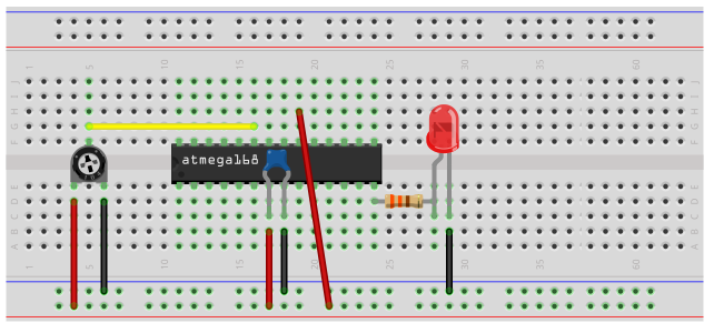
Again, it's a pretty simple circuit.
First, we need power, as all AVR circuits do. About 5 volts of power is sufficient for operation of the AVR chip. You can get this either from batteries or a DC power supply. Vcc is pin 7 and GND is pin 8. Therefore, we connect +5V of power to pin 7 and connect pin 8 to ground on the breadboard. In between both pins, we place a 0.1μF ceramic capacitor to smooth out the power of the power supply so that the AVR chip gets a smooth power line.
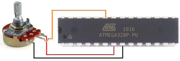
Next, we connect our potentiometer. As always, the end leads of the potentiometer can get connected to power. One end goes into positive voltage and the other gets connected to ground. The middle adjustable wiper terminal gets connected to pin PC0.
Know that a potentiometer is an analog device. It can supply a range of different voltage values anywhere from 0V to 5V. It can be any voltage in between such as 1V, 1.5V, 2.3V, etc. In contrast, digital devices only supply 2 values, either on or off. As an analog device, the potentiometer wiper terminal needs to be connected to an analog pin of the AVR chip. The analog pins are PC0-PC5 (6 pins). In our circuit, we will connect the wiper terminal of the potentiometer to the first analog pin, PC0 (pin 23).
With the wiper terminal connected to pin PC0, as we adjust the potentiometer, the voltage will adjust. As we turn it to the ground side, the voltage will decrease. And as we turn it to the VCC side, the voltage will increase. The AVR pin can detect these voltage changes and we can take whatever circuit action, we want based on certain voltage levels. For exampl,e if the voltage goes above 2.5V, we can make it so that an LED will light, as we do in this circuit example.
The only other connection we make in our hardware circuit schematic is tying AVCC to VCC. AVCC is the power supply for the analog-to-digital converter inside the AVR chip. Without its own power supply, the ADC can't function. It needs its own power source in order to operate. Therefore, we must connect it to VCC for the ADC to work. Without it, we won't be able to measure analog signals because the ADC is necessary to convert the analog signal to a digital signal, which is the only type of signal that the AVR can interpret. Therefore, you can see why tying it to AVCC is the only way an analog circuit can work.
The reason we don't have to ground the ground wire of the ADC is because both grounds on the AVR chip. So being that one GND terminal is already connected to ground, we don't have to ground the ADC ground.
And the reason we don't have to tie AREF to anything is because in our software, we connect make it so that AVCC and AREF are internally connected. Therefore, AREF will be AVCC.
These are all the connections necessary for potentiometer use with an AVR chip.
Code
Now we just need the software in order to get our circuit up and going.
The code for the AVR potentiometer circuit is shown below.
#include <avr/io.h>
#include <util/delay.h>
static inline void initADC0(void) {
ADMUX |= (1 << REFS0);
ADCSRA |= (1 << ADPS1) | (1 << ADPS0);
ADCSRA |= (1 << ADEN);
}
int main(void) {
uint16_t potentiometerValue;
uint16_t threshold_level;
threshold_level= 0b10000000;
DDRB |= (1 << PB0);
initADC0();
while (1) {
ADCSRA |= (1 << ADSC);
loop_until_bit_is_clear(ADCSRA, ADSC);
potentiometerValue= ADC;
if (potentiometerValue > threshold_level) {
PORTB= 0b00000001;
}
else {
PORTB= 0b00000000;
}
return (0);
}
}
This may seem like a lot of code, but trust me, you will get it as time goes on because it's basic once you understand what each line does.
So we first import libraries to our files. This is because this libraries contain definitions or functions we use in our code.
Next, we write code for the initialization of our ADC. We set the reference voltage to AVCC, we set the ADC clock prescaler to 1/8 of the clock speed, and we enable the ADC. All of this ADC initialization is done in code.
Next, we create 2 16-bit variables, potentiometerValue and threshold_level. Since the ADC is 10-bit ADC, meaning it holds 10 value places, the variable to hold this
10-bit ADC value must be in a 16-bit register, not an 8-bit register. We then initialize the threshold_level to 512. This is because we want the threshold level to be at the halfway turning point
of the potentiometer. Since ADC values range between 0 and 1023, the halfway mark is just about 512. Since VCC is 5V, 5V represents the full scale ADC reading of 1023. 0V represents
an ADC reading of 0. Halfway between this, a voltage of 2.5V, represents an ADC reading of 512.
When the potentiometer is outputting a voltage greater than 2.5V, the AVR will read an ADC
above 512, and the LED will turn on. If the potentiometer is turned less than halfway, so that it's outputting a voltage less than 2.5V, then the AVR chip will measure an ADC reading below 512, and
so the LED will be off.
And this is how the AVR potentiometer circuit works.
Related Resources
How to Use the LM741 Op Amp as a Comparator
How to Build an LM339 Quad Voltage Comparator Circuit
How to Build a Dark-activated Switch
How to Build a Hall Effect Sensor Circuit
How to Build a Touch Sensor Circuit
How to Build an Accelerometer Circuit
How to Build a Motion Detector Circuit
How to Build a Motion Detector Alarm Circuit