How to Build a Pushbutton Switch Circuit with an AVR
In this project, we will build a pushbutton switch circuit with an AVR chip. This is a circuit in which the AVR chip can detect when a pushbutton is pressed down.
In this circuit, we will make it so that when the pushbutton is pressed down, an LED will light up. If it is released, the LED will shut off.
This circuit demonstrates how an AVR can read digital input such as from a pushbutton switch we are using in this circuit.
With switches being so ubiquitous in electronic devices, this is a very important circuit, because you may want to build a device that incorporates a switch for operation. If you look around at you at electronic devices, how many of them incorporate switches in them? An endless amount. Everything from music players to clocks have switches, either pushbutton or another type, that allows for human-device interaction and control. Knowing how to add a switch to an AVR so that the AVR can detect when a user has pressed or turned the switch on or off is very vital.
For this circuit, a pushbutton doesn't have to be used. Really, any switch can be used such as a slide switch, a toggle switch, or so on. The circuit connections and code will be exactly the same.
Switches are useful for all types of applications including to turn a device on or off (on-or-off switch), to change a setting, or to activate particular device features.
As mentioned before, it will be made that an LED lights up when the switch is pressed down.
Components Needed
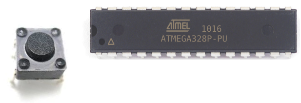
- Atmega328/168 Chip
- Pushbutton
- LED
- 330Ω resistor
- 0.1μF ceramic capacitor
- AVR Programmer
The AVR chip we will use is either the Atmega168 or Atmega328 chip. Both have the same pin layouts. If you need a reference for the pinout of the AVR chip to gain more familiarity with what each pin does, see Atmega328 Pinout. You'll need to be familiar with what each pin does in order to really know how to connect up this circuit meaningfully.
You can really use any type of pushbutton switch and there are readily available from many online retailers.
The other components we need are the LED and the 330Ω resistor in series to limit current to the LED so that it
doesn't burn out. We need a ceramic capacitor between the AVR's power pins to smooth out the power supply voltage going to the
AVR. And we need an AVR programmer to upload our code to the AVR so that it can run it.
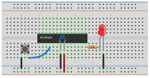
AVR Pushbutton Switch Circuit
The schematic diagram of the AVR pushbutton switch circuit is shown below.
This circuit is pretty baisc.
First, we need power, as all AVR circuits do. About 5 volts of power is sufficient for operation of the AVR chip. You can get this either from batteries or a DC power supply. Vcc is pin 7 and GND is pin 8. Therefore, we connect +5V of power to pin 7 and connect pin 8 to ground on the breadboard. In between both pins, we place a 0.1μF ceramic capacitor to smooth out the power of the power supply so that the AVR chip gets a smooth power line.
Next, connect one end of the pushbutton to ground and the other end to the AVR pin D2, which is pin 4 of the AVR. It stands for digital pin 2. This pin is capable of reading digital input from a component, which in this case is a pushbutton. A digital input is an input that can be in either 1 of 2 states, LOW or HIGH. A LOW is normally denoted with a 0. And a HIGH is normally denoted with a 1. One end of the pushbutton is connected to digital pin D2, which internally is connected to Vcc through a pull-up resistor. Thus, the pushbutton will normally be held HIGH (or at 1). However, when the button is pressed down, pin D2 now has a direct connection to ground. The voltage that was across the pushbutton now gets shunted down to ground, and pin D2 now reads LOW (or a 0). So this is how it a pushbutton works.
An LED with a 330Ω current-limiting resistor are placed in series at pin B0 of the AVR, which is pin 14.
This LED will turn on whenever the switch is pressed down.
Code
Now we just need the software in order to get our circuit up and going.
The code for the AVR potentiometer circuit is shown below.
#include <avr/io.h>
#include <util/delay.h>
int main( void)
{
PORTD |= (1 << PD2);
DDRB |= (1 << PB0);
while (1)
{
if (bit_is_clear( PIND, PD2))
{
PORTB = 0b00000001;
}
else {
PORTB = 0b00000000;
}
}
return (0);
}
So we first import libraries to our files. This is because this libraries contain definitions or functions we use in our code.
Next, we write have our main() function. We initialize pin PD2 to 1 in order to connect it to VCC through a pull-up resistor. This makes the pin connected HIGH always. This way, when the pin is HIGH, we know that the pushbutton isn't pressed. When the pin is low, then we know it has been pressed because it's now at ground level. We initialize pin PB0 to 1 so that it's made to be an output pin (not input).
The while(1) bracket is the loop of code in our circuit that runs in an endless loop and updates with new values constantly. In this section of our code, the program is searching to see if pin PD2 ever is drawn down to ground (or 0). The bit_is_clear function is true if the argument PD2 is 0. Since pin D2 is normally high and will only read 0 if it is pressed, the LED will turn on only when the pushbutton is pressed down. Otherwise, the LED will not turn on.
So this is how a pushbutton circuit works with an AVR. And the switch can really be substituted for any
other type of switch.
Related Resources
How to Use the LM741 Op Amp as a Comparator
How to Build an LM339 Quad Voltage Comparator Circuit
How to Build a Dark-activated Switch
How to Build a Hall Effect Sensor Circuit
How to Build a Touch Sensor Circuit
How to Build an Accelerometer Circuit
How to Build a Motion Detector Circuit
How to Build a Motion Detector Alarm Circuit