
How to Build a Simple Function Generator with an LM324 Op Amp Chip
In this circuit, we will show how to build a function generator circuit using an LM324 operational amplifier chip.
A function generator is a electronic device that can produce a variety of different waveforms. The one we will build can output square, triangle, or sine waveforms. Like standard function generators, the circuit allows for frequency adjustment; we get ours through a potentiometer. The circuit can also easily allow for amplitude adjustment.
The circuit works on the principle of just using op amps.
The LM324 is a quad op amp, meaning it's composed of 4 independent op amps.
In this circuit, the first op amp produces a square wave. After that, the circuit uses 2 integrator circuits to convert the square wave into triangle and sine wave signals.
Below we show how to build the circuit.
Components
- LM324 op amp chip
- 2 10KΩ resistors
- 4 100KΩ resistors
- 22KΩ resistor
- 220KΩ resistor
- 1μF ceramic capacitor
- 33nF ceramic capacitor
- 10nF ceramic capacitor
- 100KΩ potentiometer
The LM324 is a quad operational amplifier IC that we use to build this integrator op amp circuit.
The LM324 is an 14-pin chip.
The datasheet for the LM324 chip can be found at the following link: LM324 Datasheet.
In order to know how to build this circuit, you must know the pinout of an LM324, in order to connect the pins properly.
Below is the pinout of the LM324 op amp chip.
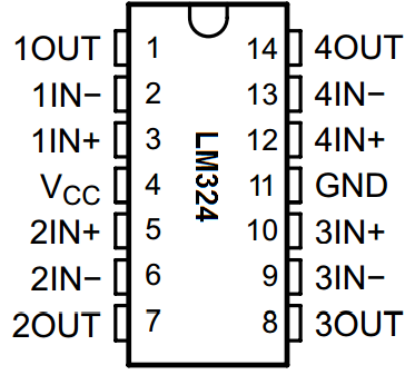
The pinout is relatively straightforward.
The LM324 has 2 power pins, pins 4 and 11.
Pin 4 is the positive voltage power supply, VCC. To this pin, we connect the positive voltage. This establishes the positive DC voltage rail for the circuit.
Pin 11, labeled GND, is the negative voltage power supply. To this pin, we connect the negative voltage. This establishes the negative DC voltage rail for the circuit.
Through these 2 pins, we establish the positive and negative DC rails from the AC signal can swing.
The LM324 can take in a maximum of up to 30V to pin 4, VCC.
All of the other 12 pins of the LM324 are the inputs or output of each of the operational amplifiers.
There are 4 operational amplifiers within the chip. Each op amp has 2 inputs and 1 output.
On the pinout above, the op amps are labeled 1, 2, 3, or 4.
The 2 inputs for each op amp are labeled IN- or IN+. The IN- pin refers to the inverting terminal of the op amp. The IN+ pin refers to the noninverting terminal of the op amp. The OUT terminal refers to the output of the op ap.
And this is breakdown of the LM324 chip.
Function Generator Circuit built with an LM324 Chip
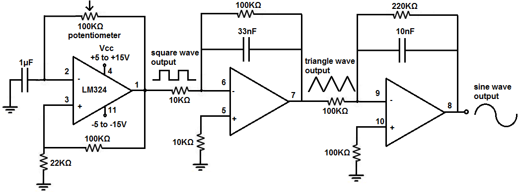
The function generator circuit we will build with an LM324 op amp chip is shown below.
The breadboard circuit of the above circuit is shown below.
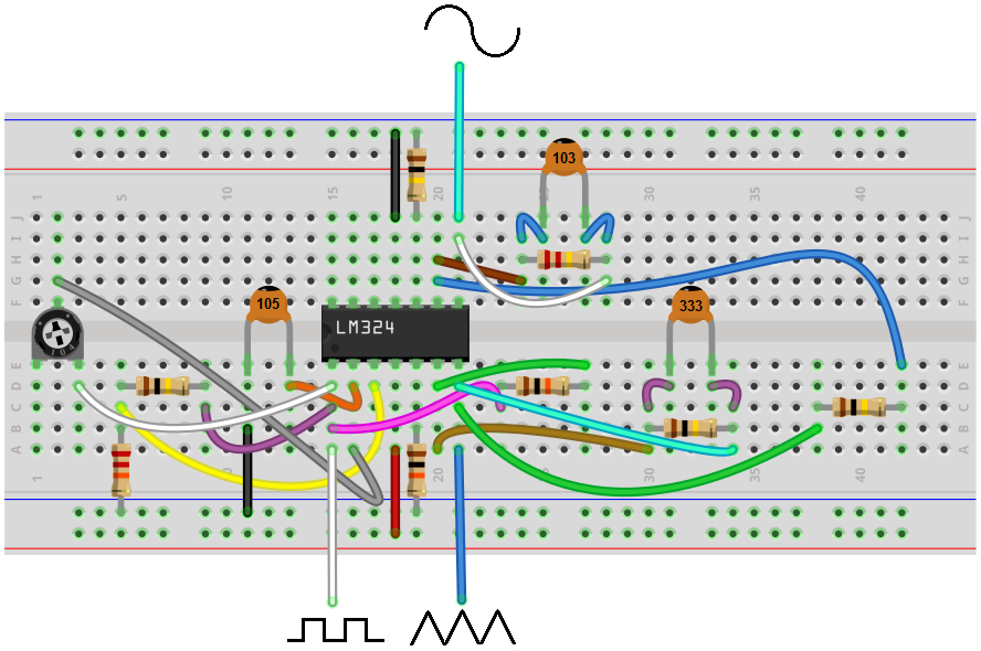
So above is the function generator chip we will build.
So the first concern is power to the circuit.
As explained above, the LM324 is powered by DC voltage through pins 4 and 11.
We feed anywhere from 5 to 15V into pin 4, VCC, and we feed anywhere from -5V to -15V to pin 11, GND.
This establishes sufficient power to the circuit so that it can operate.
So we have our first op amp. This op amp produces a square waveform. The 100KΩ potentiometer allows us to vary the frequency to the circuit. And it's the way of adjusting the frequency of the output signal.
So after the first op amp, we have a square waveform. What follows next is an integrator circuit. When you feed a square waveform into an integrator circuit, the output is a triangle waveform.
So after the second op amp, we now have a triangle waveform, as our second waveform.
We then feed this triangle waveform into another integrator circuit. When you feed a triangle waveform into an integrator circuit, the output is a sine waveform.
So after the third op amp, we have a sine waveform. This is our third waveform.
So this circuit is pretty basic. The first op amp produces a square wave. We feed this square wave into an integrator circuit, which outputs a triangle wave. We then feed this triangle wave into a second integrator circuit, which outputs a sine wave.
The 100KΩ potentiometer allows for a pretty good wide range of frequencies so that the circuit offers good frequency adjustment, as a standard function generator would.
The circuit also can easily allow for amplitude adjustment. If you're using a DC power supply to power this circuit, then all you have to do is adjust the voltage on the DC power supply to change the amplitude of the signal. If you're powering the circuit through batteries, then you'll need add the number of batteries you would need to get the maximum voltage you want and then you add a small-valued potentiometer, such as 200Ω-500Ω, to allow for voltage adjustment.
And this is how a function generator circuit can be built with an LM324 op amp chip.
The function generator is pretty solid for all basic purposes, such as home use. The signals produced can be of very high quality.
To see how this circuit operates in real life, see the video below.
Related Resources
How to Build a Voltage Gain Op Amp Circuit
How to Build a Non-inverting Op Amp Circuit
How to Build an Inverting Op Amp Circuit
How to Build a Difference Amplifier Circuit
How to Build a Differentiator Op Amp Circuit
How to Build a Summing Amplifier Circuit