
How to Build a Voltage Comparator Circuit Using an LM393
We will go over how to build a voltage comparator circuit the simplest way using the LM393 comparator IC.
The LM393 is a dual differential comparator; this means that it accepts 2 inputs for comparison.
It compares these voltage inputs and determines which is the larger value. Based on this, electronic decisions can be made based on which input is greater and which is smaller. Thus, a comparator is very useful in circuits where we measure levels and want our circuit to act a certain way based on whether the level of an input is greater or smaller than a certain threshold.
In this circuit, we will make it so that a photoresistor controls the voltage divider circuit. When the circuit is exposed to bright light, the output device will be off. When the circuit is exposed to darkness, the output device will turn on.
This circuit exploits the principle of a voltage comparator. If the voltage at the inverting terminal is higher than at the noninverting terminal, the output turns on. Vice versa, if the voltage at the inverting terminal is less than at the noninverting terminal, the output is off.
For this circuit, we will use a simple LED as the output device.
Components Needed
- LM393 IC
- Photoresistor
- 33KΩ Resistor
- 330Ω Resistor
- Potentiometer
- LED
- 3 'AA' batteries or DC power supply
The resistors don't have to be exact but should be somewhere in the near proximity of the stated values.
The potentiometer can really be any value. Normally, a 1KΩ-20KΩ potentiometer will work.
Before we actually build our comparator circuit, we first must go over in detail the pinout of an LM393 comparator IC, so that you know what each pin is and what each pin does.
An LM393 is a 8-pin chip.
The pinout is shown below:
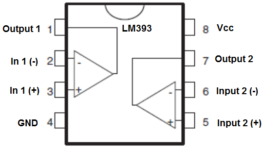
The LM393 has 2 power inputs. These are labeled Vcc and GND. Vcc is where the positive terminal of the voltage supply gets inserted into. This supply voltage can be as high as 36V. GND is where the ground wire of the voltage source gets connected to. These 2 terminals complete the power path for the LM393 chip and gives it the power it needs to function.
Apart from power, we now deal with the 2 operational amplifiers that are internally within the chip. Each op amp has 2 inputs and one output. These op amps are independent of each other, meaning each one acts independently to give its own output value (based on their 2 input values). In 1 (-) and In 1 (+) are the inputs for the op amp 1. Output 1 is the output of this op amp. In 2 (-) and In 2 (+) are the inputs for op amp 2. Output 2 is the output of this op amp.
For our circuit, we will only use one op amp; the other will be left unconnected.
Using both op amps is only needed when we deal with more complex circuits in which we need to monitor multiple levels. If we are only checking one level, then we need only one op amp.
Now that you know what each pin does, we will now explain how the chip works.
So, as explained, we have to give power to the chip in order for it to work. Once we have power to the chip, the next thing we must do is supply the op amp with 2 inputs for comparison, the 2 inputs whose voltage values we want to compare. After we have done this, we can now get an output. This output value will appear at the output terminal of the LM393.
If the voltage at the inverting terminal is greater than the voltage at the noninverting terminal, then the output of the op amp will be drawn down to ground, allowing electricity to flow from VCC to ground, turning on the output device. If the voltage at the inverting terminal is less than at the noninverting terminal, then the output of the op amp stays at VCC allowing no electricity to flow, since there is no electric potential difference across the output device.
This means that when the inverting terminal voltage is greater, the load connected to output can be powered on. When the noninverting terminal voltage is greater, the load connected to output will be powered off. So if an LED is connected to output, it will turn on when the inverting voltage is greater and turn off when the noninverting voltage falls below the inverting voltage.
So now you know the basic pins that make up the LM393 and how it works. With this understanding, we can now build our circuit.
The circuit we build will be a basic night light, which is a circuit where an LED turns on when it is dark. We are going to use a photoresistor to sense light. Remember, a photoresistor's resistance changes based on the amount of light that strikes its surface. When exposed to darkness, a photoresistor has very high resistance. When exposed to bright light, its resistance drops significantly. The amount of voltage allocated across a component is directly proportional to the amount of resistance the component offers. So if you set up a voltage divider circuit with a photoresistor and a fixed resistor, when exposed to darkness, the photoresistor will consume most of the voltage, since it has very high resistance in darkness. In bright light, the photoresistor will consume only a small portion of the voltage if an appropriate-sized resistor is used. If a good reference voltage is input into the noninverting terminal of the op amp, and the photoresistor's voltage goes above the reference voltage when exposed to darkness and below the reference voltage when exposed to bright light, we have formed a useful comparator circuit that performs a different action for when there is darkness and there is light (the LED is off in bright light and on during darkness).
And this is why comparator circuits are so useful. They are read voltage levels and be off if below a certain threshold level and on above this threshold
level.
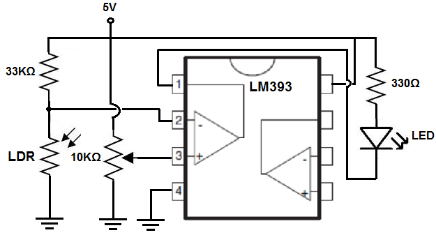
LM393 Comparator Night Light Circuit
The schematic diagram of the night light circuit is shown below:
So this is as basic of a circuit as you can get with the LM393 comparator.
Since this is a night light circuit, we want the LED on when it is dark and off during daylight conditions.
So we use the potentiometer as a calibrator. We tune it so that the LED is off during lit conditions and on during dark conditions. Tune the potentiometer so that this is the case.
This comparator circuit then compares this reference voltage with the voltage produced from the voltage divider between the photoresistor and the 33KΩ resistor. It's a really simple concept. When the photoresistor is exposed to bright light, its resistance falls well below 30KΩ. Therefore, most of the voltage gets allocated to the 33KΩ resistor and little goes across the photoresistor. Thus, the voltage produced by the voltage divider is less than the reference voltage. Therefore, the output is drawn is not drawn to VCC, which means the LED is not powered. However, during darkness, the photoresistor has a very high resistance, so most of the voltage gets allocated across it. Thus, the voltage produced from the divider circuit is above the reference voltage. Thus, the output is drawn LOW to ground, and the LED turns on.
And this is the basis of a comparator circuit.
To see how this circuit works in real life, please see the video below.
Related Resources
How to Use the LM741 Op Amp as a Comparator
How to Build a Comparator Circuit with an LM311
How to Build an LM339 Quad Voltage Comparator Circuit
How to Build a Dark-activated Switch
How to Build a Hall Effect Sensor Circuit
How to Build a Touch Sensor Circuit
How to Build an Accelerometer Circuit
How to Build a Motion Detector Circuit
How to Build a Motion Detector Alarm Circuit