How to Use the LM741 Op Amp as a Comparator
We will go over how the LM741 operational amplifier IC can be used as a comparator.
A comparator is an electronic device that can compare voltages that are on its inputs to determine which is larger or which is smaller. Therefore, we can make decisions based on which input has larger voltage.
Comparators are very useful for many different types of electronic circuits.
They serve to monitor levels.
For example, say that we are using the LM741 op amp as a comparator and we have 2 inputs we are monitoring. If one of the voltages going into the LM741 is 5V and the other is a voltage divider circuit, we can tell whether the other voltage goes below or above the 5 volts. If it goes above 5 volts, then the output of the LM741 will be high (it will be whatever voltage is supplied to the V+ terminal of the op amp). If the voltage goes below 5 volts, then the output of the op amp will be low (it will be whatever voltage is supplied to the V- terminal).
In this way, you can see how a comparator is used to check voltage levels.
Usually, a comparator will have one input that has a set (and known voltage). This serves as the reference voltage. And usually the other voltage is unknown and variable. This is usually from some type of sensor such as to measure light, heat, fluids, etc.
If we have a reference voltage (set at some value), and we have a variable voltage, using a comparator, we can tell whether the variable voltage goes above or below this reference voltage. If it goes above it, then we can make the circuit perform a certain action. If it goes below it, we can make the circuit perform a different action. For example, if it goes above the reference level, an LED turns on. If it goes below, the LED turns off.
You can see now how a comparator compares voltage values and based on these value levels perform different actions.
The LM741 is an operational amplifier IC that can function as a comparator.
It is an op amp chip that has 8 pins in total.
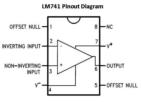
If you want a complete understanding of what each pin is and what each pin does, see LM741 Op Amp- Pinout.
The only pins we will use for our comparator circuit are 5 of the pins, V+, V-, inverting input, noninverting input, and output.
The connections for the LM741 to function as a comparator are shown below:
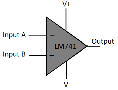
So the LM741, as in any case, needs power in order to operate. This power is placed in the terminals, V+ and V-. V+ receives positive voltage and V- is either connected to ground or receives negative voltage. This is so that the IC has the power it needs to operate. It is also biasing for the circuit. When the inverting input voltage is greater than the noninverting input voltage, the output will be V+. When the inverting input voltage is less than the noinverting voltage, the output will be V-. Thus, the voltages we supply to these terminals are really biasing for our output.
The inverting terminal and the noninverting terminal are the 2 input terminals. These are the terminals where we place both voltages to compare which voltage is the greater value. Depending on which is greater (or less) determines what occurs at the output terminal.
The last terminal we use is the output terminal. As explained, if the inverting voltage is greater than the noninverting, the output will be drawn up to V+. If the noninverting voltage is greater, the output will be drawn down to V-.
Now that we see how a LM741 can function as a comparator, let's see and examine an actual circuit in which an LM741 is used as a comparator.
Night Light Circuit Using an LM741
Below is the schematic of a night light circuit using the LM741 as a comparator.
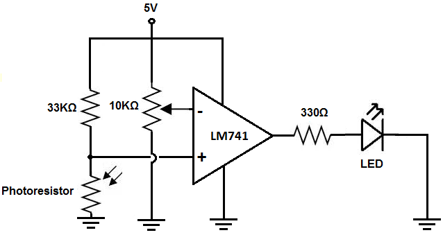
This circuit works by exploiting the fact that an LM741 operational amplifier can function as a comparator.
In this case, we are comparing a reference voltage set by the potentiometer and the voltage from the voltage divider between the photoresistor and the fixed resistor.
If the photoresistor is exposed to bright light, it will have a very low resistance. According to ohm's law, voltage that falls across a component is directly related to its resistance value (Voltage= current * resistance). Since the resistance is low in bright light, very little voltage falls across the photoresistor. Therefore, the voltage coming from the photoresistor voltage divider will be less than the reference voltage. Therefore, the output will be drawn low down to ground and the LED will not light up.
If the photoresistor is exposed to darkness, it will have a very high resistance. Therefore, a lot of voltage will fall across it. Therefore, the voltage will be greater than the reference voltage. The output of the LM741 will be drawn high and the LED will turn on.
And this is a basic, yet effective, circuit of how an LM741 operational amplifier can function as a comparator to compare voltage levels and make decisions based on these levels.
To examine how this circuit works in much more detail, see Night Light Circuit Using an LM741.
This is a video of the circuit below:
Related Resources
How to Build a Comparator Circuit with an LM393
How to Build a Dark-activated Switch
How to Build a Hall Effect Sensor Circuit
How to Build a Touch Sensor Circuit
How to Build an Accelerometer Circuit
How to Build a Motion Detector Circuit
How to Build a Motion Detector Alarm Circuit