
How to Build a Light Dimmer Circuit
In this project, we will show how to build a light dimmer circuit.
A light dimmer circuit is a circuit that is capable of dimming in or dimming out a light source.
We are going to create as simple of a light dimmer as may be possible.
All we will use for this circuit is a MOSFET, which acts as an amplifier, so that there is enough current to drive the light source. And we use a potentiometer to the gate of the MOSFET to act as a dimmer. By adjusting the resistance, we adjust the voltage being fed to the gate of the MOSFET. The voltage to this gate changes the load current, so that the lamp adjust its level of brightness. This is how the dimmer circuit works.
Again, it's very simple. All we need is a single transistor; in this case, we use a MOSFET.
This circuit is useful and can be used to act as a dimmer for practically any lighting device.
Components Needed
- 2N7000 N-Channel MOSFET
- 1MΩ resistor
- 1MΩ potentiometer
- A light source such as a lamp
So the type of MOSFET we will use is an n-channel, enhancement-type MOSFET.
By N-channel, this is referring to how the MOSFET is internally doped. When connecting an n-channel MOSFET, in order to get it work, positive voltage must be connected to the drain of the MOSFET. For a p-channel MOSFET, negative voltage would be fed into the drain of the MOSFET.
By enhancement-type MOSFET, this is referring to how the MOSFET operates.
Enhancement-type MOSFETS are MOSFETs that are normally off. When you connect an enhancement-type MOSFET, no current flows from drain to source when no voltage is applied to its gate. This is why it is called a normally off device. There is no current flow without a gate voltage.
However, if a voltage is applied to the gate lead of the MOSFET, the drain-source channel becomes less resistive. As the gate-source voltage increases more and more, the current flowing from drain to source increases more and more, until maximum current is flowing from drain to source.
An enhancement-type MOSFET is so named an enhancement device, because as the voltage to the gate increases, the current increases more and more, until at maximum level.
This is in contrast to depletion-type MOSFETs, which are normally on without any gate voltage. As voltage is applied to the gate, the transistor conducts less and less current until all current flow completely ends.
It is by far more common and much easier to find enhancement-type MOSFETs than depletion-type.
A very common and popular n-channel, enhancement-type MOSFET is the 2N7000.
The 2N7000 is very cheap, very easy to find.
The datasheet for the 2N7000 can be found at the following link: 2N7000 MOSFET Datasheet.
And it can handle current across its drain and source up to 200mA and a drain voltage of 60V.
Normally lighting devices don't need more than 200mA of current. If, in a case, it does, then you would have to use a power MOSFET instead. There are plenty available including the IRF series which can handle several amperes of current and hundreds of volts to the drain.
Besides the MOSFET, the only other components needed are the 1MΩ fixed resistor, the 1MΩ potentiometer and the lighting device used.
All are easily attainable.
Light Dimmer Circuit
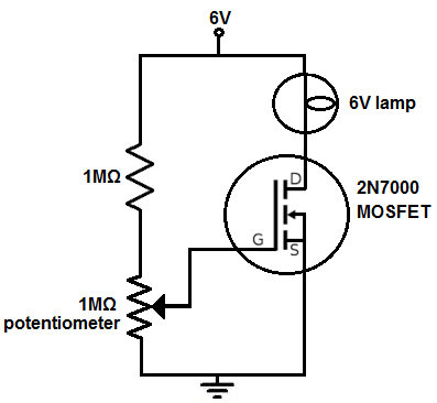
The light dimmer circuit that we will build with a MOSFET is shown below.
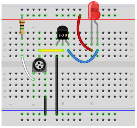
The breadboard circuit of the circuit above is shown below.
The first thing we should do is to give power to the circuit, so that it can operate.
We're going to let this circuit power off of a 6V power source, since the lamp we are lighting is a 6V lamp .
However, this may need to be adjusted, depending on the power requirements of the load you are powering. It may need or more less voltage depending on how much power the load needs.
So, how the circuits works is 2 resistors are in placed in series with each other with positive voltage at one end and the other end grounded. One resistor is a fixed resistor. The other is a potentiometer.
When the potentiometer is turned all the way so that it offers the full 1MΩ of resistance, the voltage at the gate of the MOSFET is at its maximum voltage. So when the potentiometer is turned so that it offers 1MΩ of resistance, this is the point where the light source will be at its maximum brightness for this circuit. As the potentiometer is turned so that its resistance decreases, the light source gets dimmer and dimmer until it shuts off completely.
Remember that an enhancement-type MOSFET works in that an increasing voltage increases the drain current at the output. As voltage increases to the gate, the drain current increases. As voltage decreases to the gate, the drain decreases.
It's the opposite with depletion-type MOSFETs.
Know that according to ohm's law, there is a direct relationship between voltage and resistance, according to V=IR, where v is the voltage, I is the current, and R is the resistance.
The potentiometer wiper terminal is directly connected to the gate of the MOSFET. If resistance increases or is at its maximum, the voltage at the gate increases; this in turn increases the drain current.
If the resistance decreases or is at is minium, the voltage decreases; this in turn decreases the drain current.
So this is the physics behind it.
And this is how a light dimmer circuit can be built with a MOSFET transistor.
Related Resources
How to Build a Simple Photoresistor Circuit
How to Build a Dark-activated Switch
How to Build a Dark-activated Light Circuit
How to Build a Night Light Circuit with an LM741 Op Amp
How to Build a Night Light Circuit with a NAND Gate Chip
How to Build a Light-activated Motor Circuit
How to Build a Light-activated Buzzer Circuit
How to Build a Light Detector Circuit with a NAND Gate Chip