
MQ-2 Smoke Sensor Circuit Built with a Raspberry Pi

In this project, we will go over how to build a smoke sensor circuit with a Raspberry Pi.
The smoke sensor we will use is the MQ-2. This is a sensor that is not only sensitive to smoke, but also to flammable gas.
The MQ-2 smoke sensor reports smoke by the voltage level that it outputs. The more smoke there is, the greater the voltage that it outputs. Conversely, the less smoke that it is exposed to, the less voltage it outputs.
The MQ-2 also has a built-in potentiometer to adjust the sensitivity to smoke. By adjusting the potentiometer, you can change how sensitive it is to smoke, so it's a form of calibrating it to adjust how much voltage it will put out in relation to the smoke it is exposed to.
We will wire the MQ-2 to a raspberry pi so that the raspberry pi can read the amount of voltage output by the sensor
and output to us if smoke has been detected if sensor outputs a voltage above a certain threshold. This way, we will know that the sensor has, in fact,
detected smoke.
Components Needed
- Raspberry Pi board
- MQ-2 Smoke Sensor
- MCP3002 Analog-to-digital Converter Chip
The Raspberry Pi is our microcontroller of choice for this circuit. You can really use any Raspberry Pi board, the Model A or the Model B. In our circuit, the Model B Raspberry Pi board will be used. This can be obtained from a number of different suppliers online. We recommend Farnell Element 14, whose Raspberry Pi Model B board can be found at the following link: Raspberry Pi Model B.
The MQ-2 can be obtained very cheaply, just a few bucks. A good place to look for it is on ebay, which always has auctions on them for the $2-$3 range.
Important, it is recommended that you do not obtain the standalone sensor but the whole MQ-2 board. This is because if you buy the standalone sensor, you will have to finish building the whole schematic before you can connect it to the raspberry pi. So that less work is required for integrating this with the raspberry pi, it is recommended that you buy the complete MQ-2 sensor circuit. This you can see below.
If you buy the complete board, there are 3 leads which need to be connected.
Being that the Raspberry Pi cannot process analog signals by itself (it can only process and interpret digital signals), we need an analog-to-digital converter to convert the
analog signals to digital signals, so that the Raspberry Pi can manage it. This is why we need an ADC chip and the one we will use is a MCP3002. Using this chip, the Raspberry Pi can interpret
analog signals.
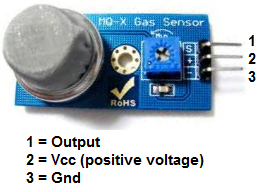
The 3 leads are Output, VCC, and GND.
It's very basic.
The gas sensor needs about 5 volts of power in order to operate. This is done by connecting 5 volts to Vcc and GND.
The Output pin gives out the voltage reading, which is proportional to the amount of smoke that the sensor is exposed to. Again, a high voltage output means the sensor is exposed
to a lot of smoke. A low or 0 voltage output means the sensor is exposed to either little or no smoke.
MQ-2 Smoke Sensor Circuit with Raspberry Pi Schematic
The circuit we will build is shown below.

The real-life diagram of the circuit above is shown below.
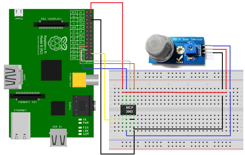
So to power the smoke sensor, we connect pin 2 of the smoke sensor to the 5V terminal of the raspberry pi and terminal 3 to the GND terminal of the raspberry pi. This gives the smoke sensor the 5 volts it needs to be powered.
The output of the sensor goes into the MCP3002 pin CH0, which is pin 2 of the MCP3002. This is one of the analog input pins of the MCP3002. The MCP3002 needs to convert this analog signal from the smoke sensor into a digital signal, which is the only type of signal that the Raspberry pi can interpret. If you're unsure of how to connect the MCP3002 analog-to-digital converter to the Raspberry Pi, see the full-length article, How to Connect the MCP3002 analog-to-digital converter to the Raspberry Pi. This will cover the pinout of the MCP3002 chip as well as all the connections to the Raspberry Pi board.
Through these connections, the Raspberry Pi can read the analog voltage output from the sensor.
We will make it in our code that if the smoke sensor voltage exceeds a certain threshold, which we will specify, we will make it so that our program outputs the statement, "Smoke detected."
Now that we have shown the hardware connections, the only other component we need is our software code.
Code
The code to read the value of a smoke sensor with a Raspberry Pi is shown below.
The botbook_mcp3002 library which you need to import into your code can be obtained at the following link: botbook_mcp3002.You just have to copy the contents of the page this redirects you to and save it as a .py file (a python file).
import time
import botbook_mcp3002 as mcp #
smokeLevel= 0
def readSmokeLevel():
global smokeLevel
smokeLevel= mcp.readAnalog()
def main():
while True: #
readSmokeLevel() #
print ("Current smoke level is %i " % smokeLevel) #
if smokeLevel > 120:
print("Smoke detected")
time.sleep(0.5) # s
if_name_=="_main_":
main()
In the first block of code, the first 2 lines, we import libraries into our code. The botbook.com library for MCP3002 is one that saves a lot of coding and makes it easy to read analog values. This above file that you have just written must be in the same directory as the botbook_mcp3002.py library. You must also install the spidev library, which is imported by botbook_mcp3002.
In our next line, we create a variable named SmokeLevel and initialize it to 0. Just as the name implies, it will hold the value of the smoke level, which will be the analog voltage output by the smoke sensor.
In our next block of code, we create a function, readSmokeLevel, which reads the analog value from the smoke sensor, which represents the smoke level. This is done by the readAnalog() function.
The next block is our main code. This repeats the program forever, whic his common for embedded devices. When
you use While True, it's recommended thtat you add some delay at the end of the loop. This gives the loop some time to pause
before executing again, kind of like a breather. All that's needed is just a few milliseconds of delay. In our code, we give it
0.5s, which is 500 milliseconds. In our main code, we call the readSmokeLevel() function, which allows us to read the smoke sensor value,
and then we output this value. If the smokeLevel is above 120, then we output the line, "Smoke detected."
And this is how our a smoke sensor circuit can be built with a Raspberry Pi.
Related Resources
How to Use the LM741 Op Amp as a Comparator
How to Build an LM339 Quad Voltage Comparator Circuit
How to Build a Dark-activated Switch
How to Build a Hall Effect Sensor Circuit
How to Build a Touch Sensor Circuit
How to Build an Accelerometer Circuit
How to Build a Motion Detector Circuit
How to Build a Motion Detector Alarm Circuit