How to Build a Motion Detector Circuit Using an Infrared Proximity Switch Sensor
It turns out that an infrared proximity switch sensor can be used to make a really good motion detector circuit.
In fact, if I were building a motion detector circuit, I would use this rather than the PIR motion sensor.
This motion detector is more accurate, in that it only triggers when an object is directly in front of the sensor.
My experience with the PIR motion sensor is that at times, it can trigger more haphazardly.
However, the infrared proximity switch sensor only triggers on if directly physically blocked, so there are really no haphazard triggerings. It's really a 100% precise. It's very clean, if motion needs to be detected.
The only disadvantage to using this as a motion-detecting device rather than say the PIR motion sensor is that it can only detect motion directly in front of it. Therefore, it cannot detect motion all around, 360°. However, most of the time, motion does not need to be detected in all directions. So this limitation can really be overcome. And if you really wanted motion detected in all directions, you could make up for this by buying multiple infrared sensors and wiring them up appropriately. In the circuits we will build, we will not be wiring up multiple sensors, but using one sensor.
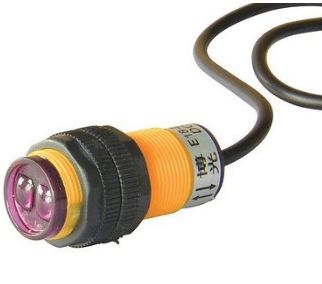
The infrared proximity switch sensor is a reflection-type photoelectric sensor which sends and receives infrared beams. Infrared proximity switches work by sending out beams of invisible infrared light. A photodetector on the proximity switch detects any reflections of this light. These reflections allow infrared proximity switches to determine whether there is an object nearby. When the infrared is able to read back the infrared beams that it sends out, then this means the path of the infrared is unimpeded, which means there is no object nearby. When the infrared sensor cannot read back the infrared beams it sends out, this means that the path is impeded and an object is in front of the sensor, which is why it cannot read back the infrared it is sending out.
Normally, when the sensor is unblocked (no object in front of it), the sensor will output a HIGH signal (about 3.5V) on its signal
line. When an object blocks the sensor so that the sensor cannot read back the infrared beams, then the sensor will output a LOW
signal (0V) on its signal line.
Differents Ways To Build the Motion Detector
There are many ways we can build a motion detector circuit using an infrared proximity switch sensor.
We can use a microcontroller such as an arduino and connect it to the sensor's signal so that the microcontroller can read what the sensor is outputting. To see how to use the infrared proximity sensor with an arduino, see How to Build an Infrared Proximity Switch Circuit using an Arduino.
If you don't want to use a microcontroller, you do not have to. There are other ways.
One is to use a NAND gate logic chip with the proximity sensor. A NAND gate can read voltages as LOW or HIGH levels. Therefore, it can read whether the infrared sensor is outputting a HIGH or LOW signal. To find out how to connect an infrared proximity sensor to a NAND gate, see How to Build an Infrared Proximity Switch Circuit with a NAND Gate.
Another alternative is to use a voltage comparator IC. A voltage comparator IC, just like a logic chip, can read voltage levels. It
can know whether a signal is HIGH or LOW. Therefore, it can read the voltage output from the infrared sensor. To find out how to connect
an infrared sensor to a voltage comparator, see
How to Build an Infrared Proximity Switch Circuit with a Voltage Comparator Chip.
Related Resources
How to Build a Motion Detector Alarm Circuit
How to Build a Vibration Alarm Circuit
How to Build a Light Alarm Circuit
How to Build a Sound Alarm Circuit
How to Build a Heat Alarm Circuit
How to Build a Tilt Alarm Circuit
How to Build a Door Alarm Circuit